
PairGain HLU-231 User manual

HIGAIN LINE UNIT
QUICK INSTALLATION GUIDE
PAIRGAIN TECHNOLOGIES, INC.
SECTION 350-231-106-01
Revision History of this guide.
Revision 01—November 25, 1997
A) Initial Release
Model List Part Number CLEI Code
HLU-231 6 150-1111-06 T1LIE1N4AA

Section 350-231-106 Revision 01
ii HLU-231 List 6
Table of Contents
Introduction ...........................................................................1
Features ............................................................................2
Compatibility ...................................................................3
Installation .............................................................................4
HLU-231 Card-Edge Connectors ....................................4
Installing the HLU-231 ....................................................5
Provisioning ...........................................................................5
Using the SEL and MODE Front Panel Buttons .............6
Default Settings ................................................................6
Using the Craft port .........................................................7
System Settings ................................................................8
Testing ..................................................................................11
Alarms ............................................................................11
Loopbacks ......................................................................12
Four-Character Diagnostic Messages ............................14
Specifications .......................................................................16
Documentation ....................................................................16
Technical Support ...............................................................16
Bulletin Board Services .................................................17
Copyright © 1997 PairGain Technologies, Inc.
PairGain and HiGain are registered trademarks of PairGain Technologies, Inc.

Revision 01 Section 350-231-106
HLU-231 List 6 1
Introduction
The PairGain®HiGain®Line Unit Model HLU-231 List 6(Part Number 150-
1111-06) is the Central Office (CO) side of a repeaterless T1 transmission
system. It is used in conjunction with the HiGain HRU Remote Unit to pro-
vide a complete HiGain High-bit-rate Digital Subscriber Line (HDSL) sys-
tem.
For more detailedinformation consult the HLU-231 List 6 Technical Practice
(Section Number 150-231-106).
The HLU-231 is not compatible with HiGain doublers.
Section 350-231-106 Revision 01
2 HLU-231 List 6
Features
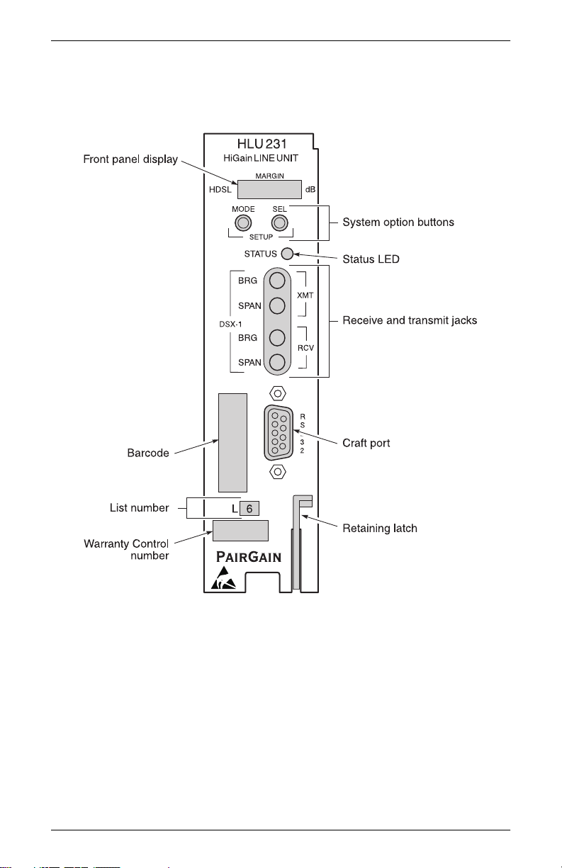
The HLU-231 Line Unit List 6 front panel features are:

Revision 01 Section 350-231-106
HLU-231 List 6 3
The HLU-231 List 6 front panel components are:
Compatibility
The HLU-231 List 6 is designed to mount in the following shelves with 220
mechanics:
• PairGain HCS-418 19-inch shelf
• PairGain HCS-417 23-inch shelf
• 220-configuration Office Repeater Bay (ORB) shelf or equivalent Small
Cross Section Shelf (SXSS)
• Kentrox T-Term shelf
• PairGain HCS-402 shelf
Name Function
Front panel display Four character LCD that provides status messages for
HDSL, S/N margin, optional settings and alarms.
System
option buttons MODE and SEL (Select) buttons used to set system
modes.
Status LED Tri-color LED that indicates system state:
Green Normal Operation
Flashing Green HDSL Acquisition
Flashing Red Minor Alarm
Red FUSE ALRM
Yellow Self Test in progress or an
HLU-231 List 6 loopback in
effect (CREM) or (NLOC)
Flashing Yellow The HLU-231intelligent loop-
back is in an ARMED state
Receive (RCV) and
Transmit (XMT) Splittingaccessandbridging"210-Bantam"-typejacks.
Craft port RS-232 connector that provides access to the mainte-
nance, provisioning, and performance monitoring inter-
face through a dumb terminal.
Retaining latch Secures the HLU-231 to the shelf in which it is installed.
Section 350-231-106 Revision 01
4 HLU-231 List 6
Installation
Upon receipt of the equipment, visually inspect it for signs of damage. If the
equipment has been damaged in transit, immediately report the extent of
damage to the transportation company and to PairGain Technologies (see
Technical Support on page 17).
HLU-231 Card-Edge Connectors
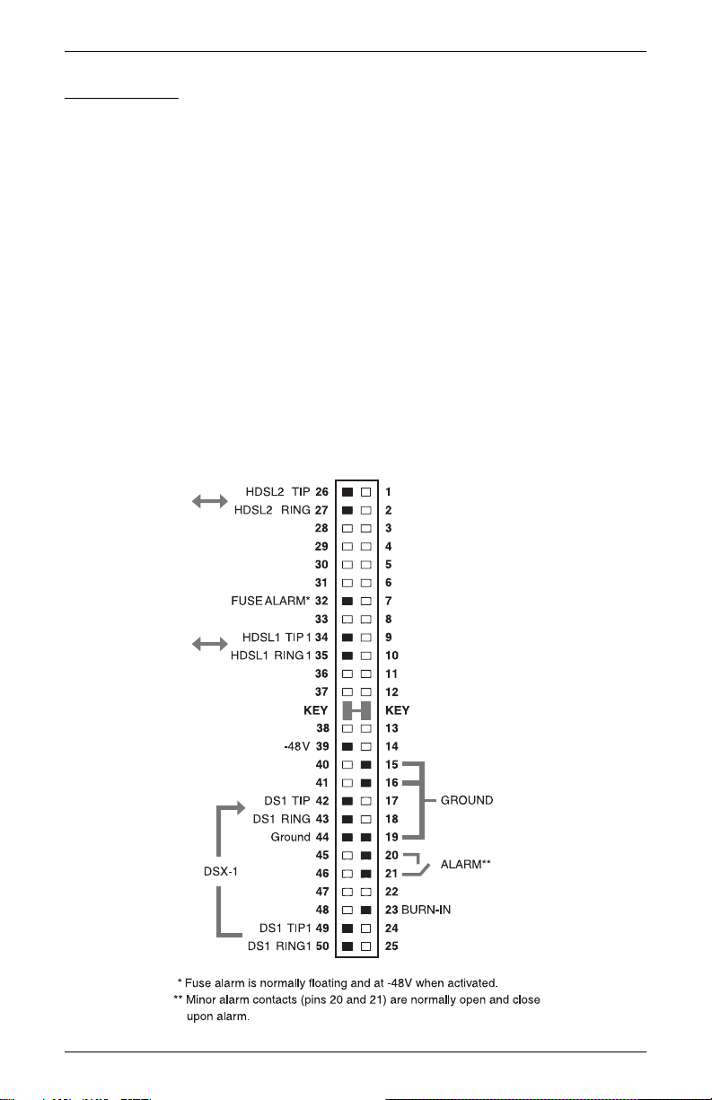
The HLU-231 card-edge connector pinouts are shown below. The following
rules apply to the HLU-231 card-edge connector:
• If the shelf uses pin 23 remove resistor R39 from the HLU-231 board.
This removes the burn-in circuit from pin 23.
• The HLU-231 uses pins 20 and 21 as alarm-relay output. The Kentrox
220 T-Term shelf uses the same pins for external equalizer output. If the
HLU-231 is installed into a Kentrox shelf, the HLU-231 ALM option
must be disabled (see Provisioning on page 6 for further information).
Revision 01 Section 350-231-106
HLU-231 List 6 5
Installing the HLU-231
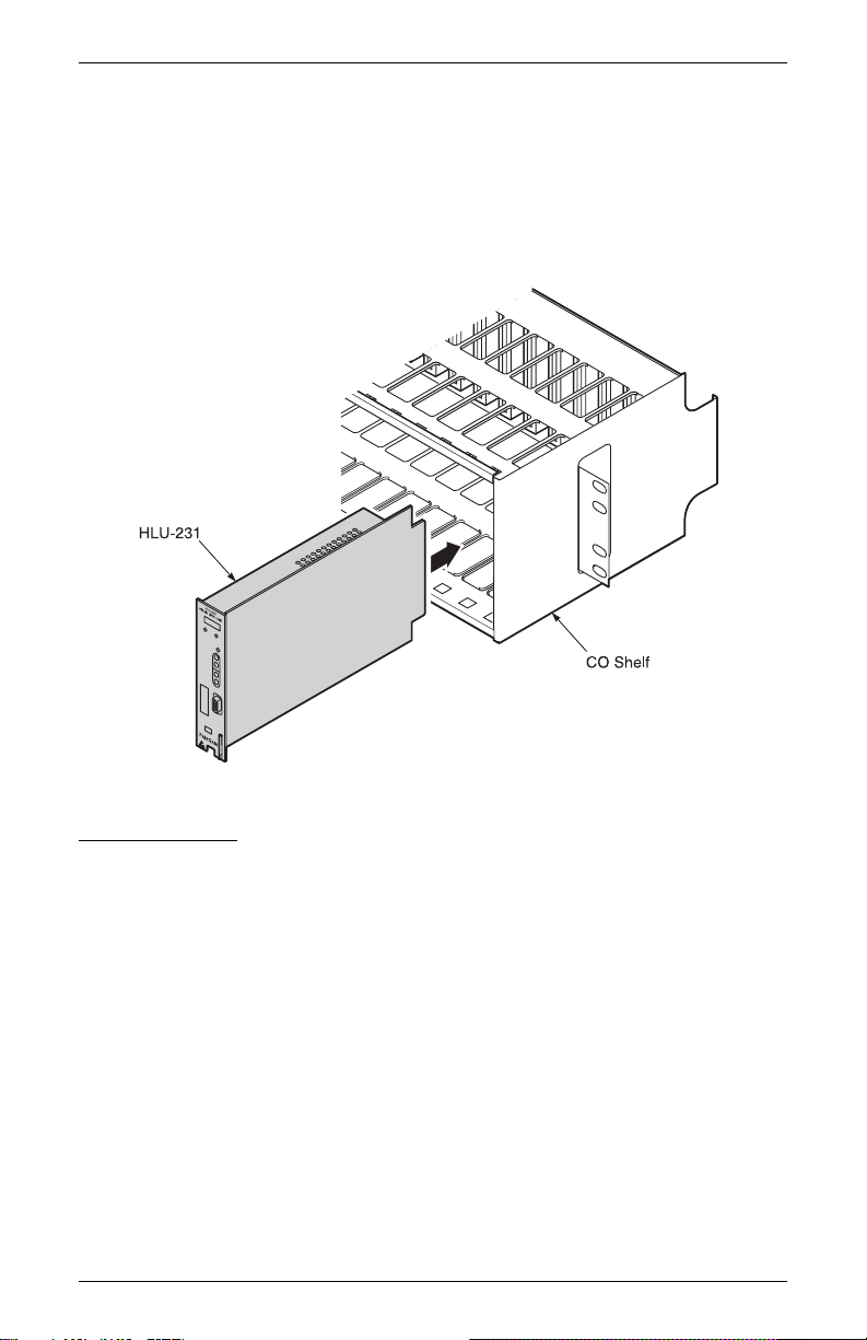
To install the HLU-231 into a PairGain shelf, slide the unit into the shelf card
guides for the desired slot, then push the unit in until it is entirely within the
card guide and the retaining latch locks into place, indicating that the unit is
properly seated:
Provisioning
The HLU-231 List 6 contains a non-volatile RAM (NVRAM) that stores the
system option settings. The options are set through the SEL (Select) and
MODE buttons on the front panel, or through a terminal connected to the
Craft port. System option settings are retained if shelf power is lost or if the
HLU-231 List 6 is unplugged.

Section 350-231-106 Revision 01
6 HLU-231 List 6
Using the SEL and MODE Front Panel Buttons
To provision the HLU-231 List 6 through the SEL and MODE front-panel
buttons:
1Press the MODE button for approximately one second. The message
displayed on thefront panelalternatesbetween the firstsystemparameter
and its current setting.
2Pressthe SEL button to step the display through all possible settings (one
at a time) of the parameter being displayed.
3Press the MODE button to select the desired parameter and move to the
next parameter. After you have configured the last parameter, the dis-
play prompts you to confirm the settings.
4Do one of the following:
•PresstheSEL button to install the settings.
•PresstheMODE button to bypass the settings.
If neither button is pressed in 30 seconds, the settings are bypassed.
Default Settings
To return the system options back to the original factory default settings:
1Press the SEL button until the DFLT NO message appears.
2Press the SEL button again and DFLT YES displays indicating the fac-
tory default values are now in effect.
To terminate the DFLT mode without setting the factory default values,
press the MODE button or do nothing for 30 seconds.

Revision 01 Section 350-231-106
HLU-231 List 6 7
Using the Craft port
The Craft port, a 9-pin RS-232 connector, on the HLU-231 front panel allows
youto use a standard RS-232cable to connect your systemto a dumbterminal
or PC running aterminal emulation program. Once connected youcan access
the maintenance, provisioning, and performance screens.
Toprovision the HLU-231 through the Craft port:
1Configure the dumb terminal to the following communication settings:
•1200 to 9600 baud (9600 baud is recommended)
•Parity: NONE
•8 data bits
•1stopbit
•Hardware Flow Control set to NONE
•VT Terminal Emulation
2Use a serial cable to connect the RS-232 COMporton the dumbterminal
to the HLU-231 front panel Craft port.
3On each screen, enter the key represented by the letterin parenthesis for
the parameter to be changed.
•Each entry of this letter scrolls the parameter to its next value.
•After all selections have been made, press to exit and to con-
firm the changes. This activates the new choices and returns control
to the Main Menu screen.
The following four user options must be set via the dumb terminal interface:
Circuit ID, Time and Date, DS0 Blocking, and Margin Alarm Threshold.
If usingtheMicrosoft Windows terminal emulation program,
from the Settings, Terminal Preference menu, deselect
ShowScroll Bars
and
UseFunction
,
Arrow
,and
CtrlKeysfor
Windows
.
E C

Section 350-231-106 Revision 01
8 HLU-231 List 6
System Settings
The asterisks (*) in the following system settings descriptions indicate the
factory default settings.
HLU-231 List 6 System Options
Mode Selection Description
EQL EXT* Selects extended equalizer.
0Sets the internal equalizer to DSX-1 for 0 - 133 feet.
133 Sets the internal equalizer to DSX-1 for 133 - 266 feet.
266 Sets the internal equalizer to DSX-1 for 266 - 399 feet.
399 Sets the internal equalizer to DSX-1 for 399 - 533 feet.
533 Sets the internal equalizer to DSX-1 for 533 - 655 feet.
ZBTS ON Selects the Extended Superframe (ESF) frame ZBTSI
mode.
OFF* Deslects the ESF frame ZBTSI mode.
LPBK DIS Configures the HLU-231 to ignore the 2 in 5 Smart-Jack
loopback command.
ENA* Enables theHLU-231 to respond to the 2 in5 Smart-Jack
loopback command.
LBTO NONE Disables automatic time-out cancellation of all loopbacks.
20 Sets automatic cancellation of all loopbacks to20 minutes
after initiation.
60* Sets automaticcancellation of all loopbacks to60 minutes
after initiation.
120 Sets automatic cancellation of all loopbacks to 120
minutes after initiation.
ALM DIS* Opens the relay alarm contacts, if closed, and prevents
another relay alarm closure from occurring.
ENA Enables activation of the minor alarm relay when a minor
alarm condition occurs.
Other manuals for HLU-231
8
This manual suits for next models
1
Table of contents
Other PairGain Switch manuals


