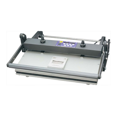
P. Energy L150A Manual

……………………………………………… USER AND MAINTENANCE HANDBOOK L150A
P.Energy
P.Energy P.Energy
P.Energy
1 - 30
USER AND MAINTENANCE HANDBOOK
LAMINATOR L150A
SERIAL NUMBER:

……………………………………………… USER AND MAINTENANCE HANDBOOK L150A
P.Energy
P.Energy P.Energy
P.Energy
2 - 30
GENERAL INDEX
1. GENERAL INFORMATION
1.1. GENERAL INSTRUCTION
1.2. MACHINE SERIAL NUMBER
1.3. GENERAL DESCRIPTION OF MACHINE COMPONENTS
1.4. GENERAL DESCRIPTION OF LAMIANTION PROCESS
1.5. INTENDED USE OF THE MACHINE
1. . WARRANTY
2. SAFETY
2.1. INTRODUCTION
2.2. GENERALI GENERAL SAFETY RULES
2.3. MACHINE CONNECTIONS
2.4. GROUNDING SYSTEM
2.5. MACHINE SAFETY DEVICES
2. . IDENTIFICATION OF RESIDUAL RISK
3. INSTALLATION
3.1. INTRODUCTION
3.2. FONDATIONS
3.3. EQUIPMENT FOR LIFTING & TRANSPORTING
3.4. ELECTRICAL CONNECTION
3.5. PNEUMATIC CONNECTION
3. . HYDRAULIC CONNECTION
3.7. DESCRIPTION OF WORKING CYCLE AND ALLARMS MACHINE
3.7.1. DESCRIPTION OF PUSHBUTTONS OPERATOR PANNEL
3.7.2. DESCRIPTION OF TOUCH SCREEN PAGES
3.7.3. MACHINE START-UP
3.8. TROUBLESHOOTING
4. LAMINATION INSTRUCTION
5. MAINTENANCE
5.1. ORDINARY MAINTENANCE
5.1.2 REPLACEMENT MEMBRANE
5.2. EXTRAORDINARY MAINTENANCE
5.2.1. REPLACEMENT ELECTRICAL RESISTORS
5.2.2. REPLACEMENT THERMOCOUPLES
5.2.3. REPLACEMENT O-RING
6. MACHINE DISPOSAL
7. RECCOMENDED SPARE PARTS
8. MECHANICAL COMPONENT LIST
9. SUPPORTING DOCUMENTS
A. CE CERTIFICATE OF CONFORMITY
B. ELECTRICAL SCHEME
C. PNEUMATIC SCHEME
D. VACUUM PUMP MANUAL
E. INTERNAL TESTING REPORT

……………………………………………… USER AND MAINTENANCE HANDBOOK L150A
P.Energy
P.Energy P.Energy
P.Energy
3 - 30
1.
GENERAL INFORMATION
1.1. GENERAL INSTRUCTION
• Questo
This manual describes the correct way to use the laminator L150A for photovoltaic panels with maximum dimension
1500x1000mm, made and sold from this company:
P.ENERGY SRL
Via dell’artigianato, 12 – 35014 Fontaniva (PD) – ITALY
Phone: +39 (0)49 79 190
Fax: +39 (0)49 79 8 77
Web Site: www.penergy.it
e-mail: [email protected]
• THIS MANUAL IS PART OF THIS MACHINE AND CONTAIN ALL NECESSARY INFORMATION CONCERNING USE AND
MAINTENANCE.
• IF YOU DON’T PAY ATTENTION TO INSTRUCTION AND RACCOMANDATION OF THIS MANUAL THE GUARANTEE IS NOT
ACTIVE
• IT’S PERMITTED TO USE THE MACHINE ONLY TO WELL-TRAINED OPERATORS.
• THE OPERATOR HAS TO READ CAREFULLY THIS MANUAL BEFORE TO INSTALLATION AND START-UP.
• The Manufacturer reserves to suspend the production of some machine model, to modify characteristic and drawings
without obligation advice.

……………………………………………… USER AND MAINTENANCE HANDBOOK L150A
P.Energy
P.Energy P.Energy
P.Energy
4 - 30
1.2. SERIAL NUMBER
In order to identify the laminator it’s necessary to recognize the following specification data plate fixed on
side machine.
Data on CE identification plate
Example:

……………………………………………… USER AND MAINTENANCE HANDBOOK L150A
P.Energy
P.Energy P.Energy
P.Energy
5 - 30
1.3. GENERAL DESCRIPTION OF MACHINE COMPONENTS
The laminator is a machine controlled from an operator that laminate together all material introduced inside. Through a program is it possible to control the
parameters like temperature level, the vacuum and the working time.
The laminator is mainly composed of two parts: An aluminum plate is heated through a series of electric resistances or cooled through an hydraulic circuit
according to set up parameters and by an hermetic shifting cover.
The electrical cabinet is fixed in front of machine and inside the frame is positioned the pneumatic circuit, protected by sheet guard, included the vacuum pump
and hydraulic circuit.
On the back side there are the electrical, pneumatic, hydraulic feeding.
The area inside the cover is protected by two light barriers fixed on the corner of the aluminium plate .
The laminator is controlled by LCD keyboard supported through a mobile arm.
View of Laminator component
12
13
lamination chamber
1 2 3 4 5 7 8 9 10 11
left side sheet guard
15
1
18
19
Pos Description
1
Adjustable fe
et
2
left front side sheet guard
3
electrical cabinet
4
Lamiantor frame
5
Base machine
laminator cover
7
cover vacuum gauge
8
plate vacuum gauge
9
Light barrier mirror on the
right front side
10
Mobile arm of operator panel
on left front side
Pos Description
11
electrical pannel
12
Light barrier sender on right
front side
13
Light barrier mirror on the left
back side
15
Membrane frame
1
Membrane
18
heating plate
19
plate frame

……………………………………………… USER AND MAINTENANCE HANDBOOK L150A
P.Energy
P.Energy P.Energy
P.Energy
6 - 30
20
40
21
22
23
Back view without cover
24
25
2
27
28
29
30
31
32
33
34
Pos
Description
20
Column cover
21
inlet pneumatic feeding
22
hydraulic circuit outlet
23
inlet hydraulic circuit
24
upper bearing for ball bearing
screw
25
Siren
2
Blu lamp
2
7
Red Lamp
28
Green lamp
29
sectional guide
30
Slide
31
upper point limit switch
32
Cable carrier chain system
33
ball bearing nut
34
ball bearing screw
35
lower bearing connection of
ball bearing screw
3
cover el. motor
37
reduction gear of cov
er
electrical motor
38
pneumatic pression regulator
39
vacuum pump
40
Hook
35
3
37
38
39
LENGHT=19
00mm
WITH=2100mm
HIGHT=2200mm
WEIGHT=2000Kg

……………………………………………… USER AND MAINTENANCE HANDBOOK L150A
P.Energy
P.Energy P.Energy
P.Energy
7 - 30
1.4. GENERAL DESCRIPTION OF LAMINATION PROCESS
DESCRIPTION OF WORKING CYCLES:
1. PRESTART SETPOINT REACHED
The starting parameter are reached in automatic mode according to setting recipe and the end phase is diplayed by signal lamp
2. SANDWICH INTRODUCTION
Operator introduce in manual mode the sandwich
3. LAMINATION CYCLE
The automatic lamination cycle start when the operator push the two hand pushbutton and the cover move to the close position before the
beginning of lamination process.
Following inside the hermetic chamber between cover and plate the vacuum is reached in order to remove the air residue between the
sandwitch, after a membrane lower and exert uniform pressure over the panel.
Simultaneously a constant temperature is maintained for a programmed time in order to join the component
Next step is cooling the plate by an hydraulic circuit and to reset the pressure value inside the laminator chamber.
All parameter are edited by the operator panel
4. LAMINATED SANDWICH EXRACTION
At the end of recipe the cover move in automatic mode to the upper point and the laminated panel is removed.
PRESTART
SETPOINTS
REACHED
SANDWICH
INTRODUCTION
LAMINATION CYCLE
:
1. VACUUM
2. HEATING AND PRESSURE
3. COOLING
LAMINATED SANDWICH
EXTRACTION

……………………………………………… USER AND MAINTENANCE HANDBOOK L150A
P.Energy
P.Energy P.Energy
P.Energy
8 - 30
NOTE: In order to adjust the temperature inside the laminator chamber the heating plate is divided in areas with 3 heating resistor and 1
thermocouple probe per area.
The heating plate is even cooling by a dedicated circuit.
Follow the plate layout:
CIRCUIT ON HEATING PLATE
Coolin circuit in
Coolin circu
it out
Resistor
T
hermocouples

……………………………………………… USER AND MAINTENANCE HANDBOOK L150A
P.Energy
P.Energy P.Energy
P.Energy
9 - 30
1.5. INTENDED USE OF THE MACHINE
The
P.ENERGY L15
0A
laminator is designed only to be used to with maximum dimension panel
15
00
x1000mm
.
The maximum thickness is 40mm.
The P.ENERGY L150A laminator work with Standard/FAST/Ultra fast cure EVA
P. Energy suggest to work with the follow raw materials:
glass: LIPIK GLASS ULTRALIGHT
lamianted: TEDLAR CTE COVEME
cells: GINTECH 4’’,5’’, ’’
eva: STANDARD/FAST/ULTRAFAST CURE ETIMEX
the laminator in your possession has been designed such a way that’s operated by a single operator who shares the cycle of work and visions
successful.
The technical specifications such as: worked hours, Quantity of Production, and type of finished products are specified at the time of the bid.
1.6. ARRANTY
The warranty refers to the contractual terms agreed with the customer, in any case:
THE WARRANTY STOP IF:
• Manual instructions are not respected
• There will be modifications without authorization
• Programmed maintenance is not followed
• The machine will be used from a different purpose from that designed
•
The machine will be done from not licensed people

……………………………………………… USER AND MAINTENANCE HANDBOOK L150A
P.Energy
P.Energy P.Energy
P.Energy
10 - 30
2.
SAFETY
2.1. INTRODUCTION
It is forbidden to use the machine for reasons other than that describe above, and/or by person who are not suitably trained.
2.2. GENERAL SAFETY RULES:
1. Always keep clean and tidy the work area
2. Do not leave tools or spanners on the machine, or near to it. After any maintenance work or the replacement of accessories, check carefully, before
switching on the machine.
3. Always be sure that you are in a safe position with respect to the machine in a secure, well-balanced position.
4. Never leave the machine unsupervised
5. All the operations of normal or special maintenance carried out on the machine, as well as cleaning ad running the machine must only be undertaken
by trained personnel
. Any normal or special maintenance work must only take place with the machine stopped and electrical supply cut off, the pneumatic and hydraulic
plant must only be carried when the pressure has been released from the equipment
7. Before each work shift, ensure that the safety system operate correctly
8. The working place have to be protected from atmospheric conditions
2.3. MACHINE CONNECTIONS:
It is responsibility of the client to set up the electrical and pneumatic supply system of a suitable size to withstand small power surges of the laminator, see data
sheet present on the SUPPORTING DOCUMENTS
The electrical and pneumatic supply system to be connected to the plant must only be carried out by qualified personnel, and carried out according to general
regulations for electrical plant installation
2.4. GROUNDING SYSTEM
It is responsibility of the client must be connected to an efficient grounding system
2.5. MACHINE SAFETY SYSTEM
• MECHANICAL
a) Protective panel in painted sheet metal, protecting the electrical and pneumatic plant
b) Protective panel in painted sheet metal, protecting the danger area
c) The cover movement is controlled by a sensor maximum openness and a sensor minimal.
d) The access door to the electrical panel is fitted with a main switch for the main machine electrical power supply. This is of the type that can be
padlocked and is fitted with mechanical lock, which does not allow the electrical cabinet to be opened unless the switch is at the “0” position.
e) The speed of descent and ascent of the cover is sufficiently slow so that the operator has the time to evaluate the potential risk.
f) The laminator is designed to be used by a single operator to operate the movement of the cover must use the special command with two hands.
• ELECTRICAL
a) All perimeter of laminator is protected by an infrared barrier that blocking the cover movement in case of introductions.
b) The electrical circuit is protected by thermal-magnetic circuit breaker and fuse
• TOWER SIGNAL LAMP:
- Red lamp: danger
-Green lamp: fixed lamp =automatic cycle; Blinking lamp = pre-start conditions reached.
-Blue lamp: cooling circuit activated
• SIREN, it signals with an acoustic signal, the alarm presence ( fixed sound), and the cover movement ( Intermittent sound)
2.6. IDENTIFYING THE ZONES OF RESIDUAL RISK NEAR THE MACHINE
the area along the entire perimeter of the laminator to a width of 1 meter can be a source of hazard for the operator if the rules of behavior are not respected
and if the operator fails adequately monitor the working area

Table of contents