
Oxygen 8 VENTUM Series User manual

INSTALLATION
MANUAL
VENTUM SERIES

Table of Contents
1. General Information 3
2. Installation 4
2.1 Unwrapping the Product 4
2.2 Assembly 4
2.3 Weights 5
2.4 Installation 5
2.4.1 Ceiling Mount 5
2.5 Installation of Accessories 7
2.5.1 Coupled Accessories 7
2.5.2 Decoupled Accessories 9
2.6 External Sensors 10
2.6.1 Supply Air Temperature Sensor 10
2.6.2 Pressure Sensor 10
2.6.3 CO2/VOC Sensor 11
2.6.4 Combination Temperature 12
/Humidity Sensor
3. Access Requirements 13
4. Lifting Requirements 13
5. Electrical Hook-Ups 14
5.1 Electrical Information 15
5.2 1PH Electrical Hook Up (2 Fans) 16
5.3 3PH Electrical Hook Up (2 Fans) 17
5.6 1PH Lite Electrical Hook Up (2 Fans) 18
5.7 3PH Lite Electrical Hook Up (2 Fans) 19
6.0 Wiring Diagrams 20
6.1 Ventum 240V, Single Phase, S1 21
6.2 Ventum 240V, Single Phase S2 22
6.3 Ventum, Three Phase, S1 23
6.4 Ventum, Three Phase, S2 24
6.5 Field Wiring, DX Coil, EKE 25
6.6 Field Wiring, DX Coil, Electric Reheat, EKE 26
6.7 Field Wiring, Electric Preheat, DX Coil 27
Electric Reheat, EKE
6.8 Field Wiring, Electric Preheat, DX Coil, EKE 28
6.9 Field Wiring, Damper Wiring 29
6.10 Field Wiring, Electric Reheat Wiring 30
6.11 Field Wiring, Electric Preheat, 31
Electric Reheat Wiring
6.12 Field Wiring, Electric Preheat Wiring 32
6.13 Field Wiring, Cooling Water Coil 33
6.14 Field Wiring, Humidity Control 34
6.15 Field Wiring, Combi Coil 35
6.16 Field Wiring, Hydronic Preheat 36
6.17 Field Wiring, Occupancy Mode 37
6.18 Field Wiring, Hydronic Reheat 38
6.19 Field Wiring, Fire Alarm 39
6.20 Field Wiring, DX Coil, Hydronic Reheat 40
EKE, Bypass
6.21 Field Wiring, CO2 Control, 41
External Bypass

Installation Manual Ventum Series
3
This manual includes important instructions for safe
connection of the Heat Recovery Ventilator (HRV) or
Energy Recovery Ventilator (ERV). Before connecting
the unit, please read carefully and follow all of the
instructions below! The manufacturer reserves the
right to make changes, including changes in the
technical documentation, without previous notification.
Please keep this manual for future reference.
Consider this manual a permanent part of the product.
This manual will show the manufacturers'
recommended installation method. Please note that
local codes and regulations may override these
recommendations. The installation must follow local
codes and standards.
The National Electric Code (NEC), the National
Fire Protection Agency (NFPA), and the Canadian
Electrical Code (CEC) must be followed. Installation
of this product must be performed by a qualified and
accredited professional in conformance with local and
national codes, standards and licensing requirements.
Warnings and Caution
Warnings and cautions appear at the appropriate
sections throughout this manual. Please read these
sections carefully.
Warning
This sign indicates a potentially hazardous situation,
which could result in death or serious injury if not
avoided.
Caution
This sign indicates a potentially hazardous situation,
which may result in minor or moderate injury if not
avoided. It may also alert against unsafe practices.
Caution
This label indicates a situation that may result in
equipment or property damage only accidents.
1.0 General Information

Installation Manual Ventum Series
4
2.1 Unwrapping the Product
When removing the shrink wrap, be cautious with
knives and sharp tools to prevent scratching the
paint.
The HMI, pressure sensor, external duct pressure
sensor and all other optional field components will be
found in the electrical box or fan compartment. They
are secured there for transport and to easily find
them on the job site.
2.2 Assembly
Remove the middle panel for wiring access. Fans
and filters are accessible via the bottom doors. Fans
should be pre-wired and no assembly is required.
Use the following steps to disassemble the fan
section from the core section.
1. Remove the cover from the fan.
2. Undo the screw terminals that are holding the
power wires and the communication wires.
*See back of manual for electrical drawings.
3. Loosen the cable glands and pull the wires out of
the motor.
4. Pull the pressure tube from the nozzle port on
the fan bell mouth.
5. Push the pressure tube and all cables back into
the core section, through the rubber grommets
that are on the fan wall.
6. Repeat steps 1 ― 5 for the other fan.
2.0 Installation
1 2 4
3 5
Unit Wrapped
for Shipping
4x Corner
Installation Manual Ventum Series
5
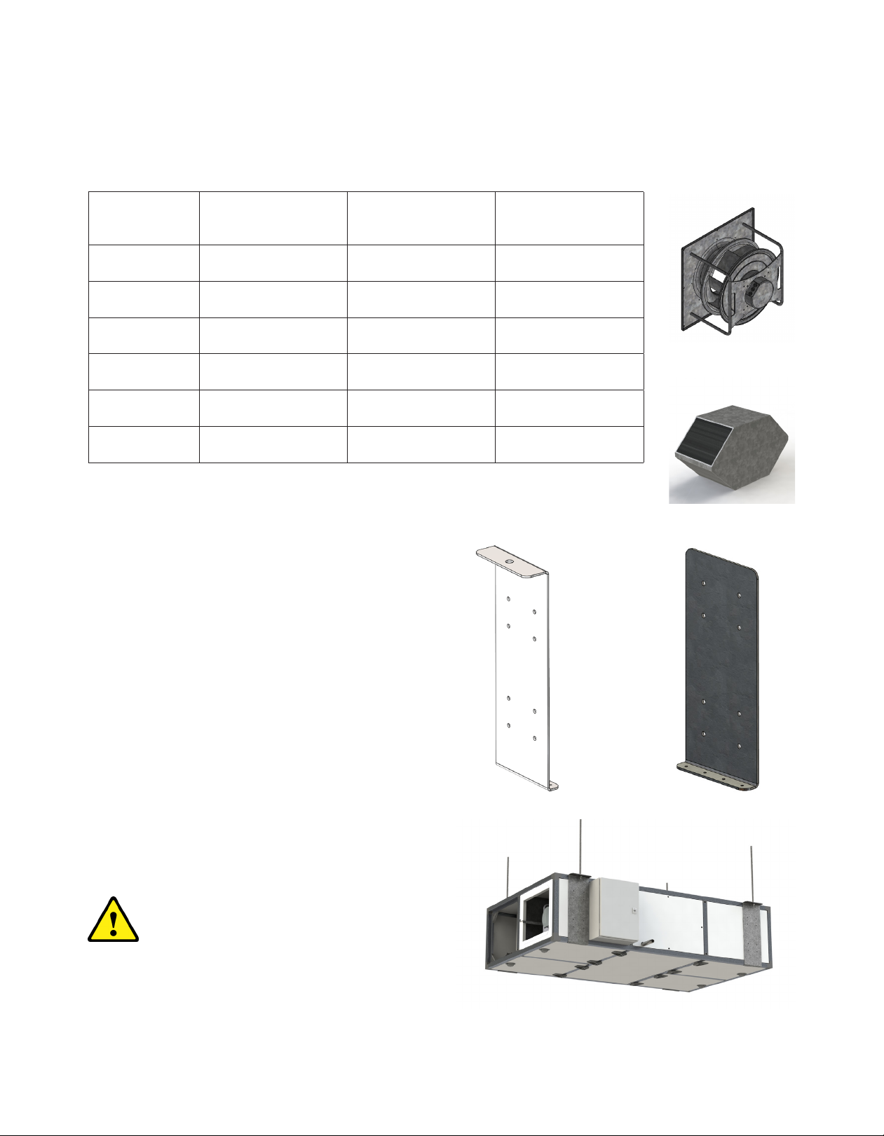
2.3 Weights
Model Fan (A) lbs. Core (B) lbs. Total Weight lbs.
H05 27 13 450
H10 28.7 13 620
H15 37.5 22 720
H20 37.5 22 820
H25 48.5 64 1130
H30 48.5 64 1300
A
B
2.4 Installation
2.4.1 Ceiling Mount
Ventum is available exclusively for ceiling mount/
horizontal applications with inner and outer brackets
only. The hanging brackets are supplied loose with
the necessary hardware to install them. They are not
shipped assembled due to the variability of installation
access on job sites. The front panel of the unit must be
removed to slide the core into the unit.
Each hanging bracket is composed of two pieces: an
inner component and an outer component. The units
are designed to have four sets of brackets to support
the unit.
Note Depending on the ducted opening location
selected during the design phase, the location of
the brackets will vary. Please consult your submittal
drawings for specific locations.
Inner
Bracket
Outer
Bracket
Warning
The unit must be installed with both the inner and outer
bracket. Each unit must also have all four brackets
installed to meet these guidelines. Ceiling Mounted Unit

Installation Manual Ventum Series
6
Assembly of Hanging Brackets
1. Locate the position of the brackets on the outside
of the unit.
2. Mark the 8 hole locations and drill to allow for
the ¼" bolt. 32 - ¼" bolts, 32 - ¼" lock nut, 32 - ¼"
washers and 64 - ¼" washers have been provided
with the unit.
3. Assemble the hanging bracket by aligning the 8
holes of the outer bracket through the unit and
with the inner bracket. Note: the inner component
should be oriented so that its flange is pointing to
the ceiling, and the outer bracket has the single
hole pointing to the ceiling.
4. Install the 8 bolts. Caution - Do not over tighten
and crush the panel.
5. Install 4 tek-screws in the flange portion of the
inner bracket and secure it to the top casing of the
unit.
6. Install 4 tek-screws in the lower flange of the outer
bracket to secure it to the bottom frame of the unit.
7. Repeat steps 1 through 6 for the remainder of the
brackets.
8. The hole in the outer brackets are designed for a
½" threaded rod to hang the units by.
Bracket Alignment

Installation Manual Ventum Series
7
2.5 Installation of Accessories
2.5.1 Coupled Accessories
Coupled Accessory with Ceiling
Mounted Unit
Mounted Coupled Accessory

Installation Manual Ventum Series
8
Corner brackets come pre-installed with each Ventum unit. Accessories should be independently supported with
Unistrut on the end farthest from the unit. Base mounted accessories that are connect to a duct connection in the
lower position of the unit will come with matching base rails.
Accessories that are to be connected to a duct connection in the upper position will need to be supported
externally.
12

Installation Manual Ventum Series
9
2.5.2 Decoupled Accessories
Ceiling hung decoupled accessories will not come with hanging brackets and can be supported in the ceiling with
horizontal brackets and threaded rod or equivalent.

Installation Manual Ventum Series
10
2.6 External Sensors
2.6.1 Supply Air Temperature Sensor
TTH-6202 sensors are installed in the ventilation
duct using the accompanying bracket, which must
be attached to a firm, level surface by means of
two screws. The supply voltage is provided via the
Modbus connection. TTH-6202 has a pre-fitted cable,
which is equipped with a standard RJ12 connector.
The cable may be extended up to 50 m using a
Category 3 extension cable. The sensor must be
mounted according to, and must be aligned parallel to
the air flow in the center of the duct.
*Sensor must be installed a minimum of 5' from the heating or cooling module.
2.6.2 Pressure Sensor
Sensor must be installed ⅔ of the way down the duct in the
duct path that would result in the most pressure drop.
Supply Air
Return Air
5'*
Supply Air
Table of contents
Other Oxygen 8 Fan manuals


Popular Fan manuals by other brands

ELTA FANS
ELTA FANS H03VV-F installation guide

Hunter
Hunter 20714 Owner's guide and installation manual

Emerson
Emerson CARRERA VERANDA CF542ORB00 owner's manual

Hunter
Hunter Caraway Owner's guide and installation manual

Panasonic
Panasonic FV-15NLFS1 Service manual

Kompernass
Kompernass KH 1150 operating instructions




