OMCR VDI3366 User manual
Use and maintenance manual
complete of EC conformity declaration
LIFTING BRACKET
WITH ROPE STOP SAFETY
VDI3366
Item code: B01.11
S. Maurizio C.se - 18/12/2020 www.omcr.it
Via Quarantelli 8 -10077 - S. Maurizio C.se - Italy
T+39 011 996 46 11 - F+39 011 996 46 46
C.F./P.IVA 07677130010
info@omcr.it - www.omcr.it
ENGLISH ITALIAN GERMAN SPANISH FRENCH

2. Use and maintenance manual B01.11 S. Maurizio C.se - 18/12/2020 www.omcr.it
INDEX
1. RISKS EVALUATION . . . . . . . . . . . . . . . . . . . . . . . . . . . . . . . . . . . . . . . . . .3
2. SYMBOLS AND WARNINGS CLASSIFICATION . . . . . . . . . . . . . . . . . . . . .3
3. USE . . . . . . . . . . . . . . . . . . . . . . . . . . . . . . . . . . . . . . . . . . . . . . . . . . . . . . .4
4. HANDLING AND STORAGE . . . . . . . . . . . . . . . . . . . . . . . . . . . . . . . . . . .10
5. MAINTENANCE . . . . . . . . . . . . . . . . . . . . . . . . . . . . . . . . . . . . . . . . . . . . .11
EC CONFORMITY DECLARATION . . . . . . . . . . . . . . . . . . . . . . . . . . . . . . . .12
3. Use and maintenance manual B01.11 S. Maurizio C.se - 18/12/2020 www.omcr.it
1. RISKS EVALUATION
The matters of following pages refer to a classic use of lifting brackets and they can’t forecast unspecified
applications. For this reason each user must provide to his own risks evaluation and he must consider this
manual as general reference support and as a summary of possible matters. To define the employ-procedures,
to spread information and to check the compliance of these ones it’s a duty and a responsibility of the user.
The lifting brackets have to be used as couplets for ropes and they allow users to make on safety the following
actions: LIFTING / HANDLING / OVERTURNING; the material, the production and the quality-check of all
OMCR lifting pins comply with the Directive 2006/42/EC requirements; all OMCR lifting elements have been
tested with a static safety factor even to a minimum 1.5, all materials have been analyzed according to UNI
EN 10204, samples of all materials have been subjected to tensile stress test according to UNI EN 10002.
Calculations and risk assessments have been made according to VDI3366 norms.
An improper or opposed use in reference to the prescriptions treated in this manual, deletes this EC
conformity declaration and relieves OMCR from any responsibility.
WARNING
According to ISO 3864-2, ANSI Z535.6, ANSIZ535.4 norms, in this manual are classified the following safety
messages and symbols:
2. SYMBOLS AND WARNINGS CLASSIFICATION
WARNING
WARNING
NOTE
It indicates a hazardous situation which, if not avoided, could result
in death or serious injury.
It indicates a hazardous situation which, if not avoided, could result
in minor or moderate injury.
It indicates advices on use or other especially helpful informations.
It indicates general warning symbol.
It indicates hazard of crushing consequent to an accidental fall or overturning
of the load.
It indicates hazard of crushing.
It indicates musculoskeletal disorders for the handling of the loads.
It indicates forbidden actions or uses.
It indicates mandatory actions to avoid hazards.
It indicates that it is forbidden to stop or to transit.

4. Use and maintenance manual B01.11 S. Maurizio C.se - 18/12/2020 www.omcr.it
3. USE
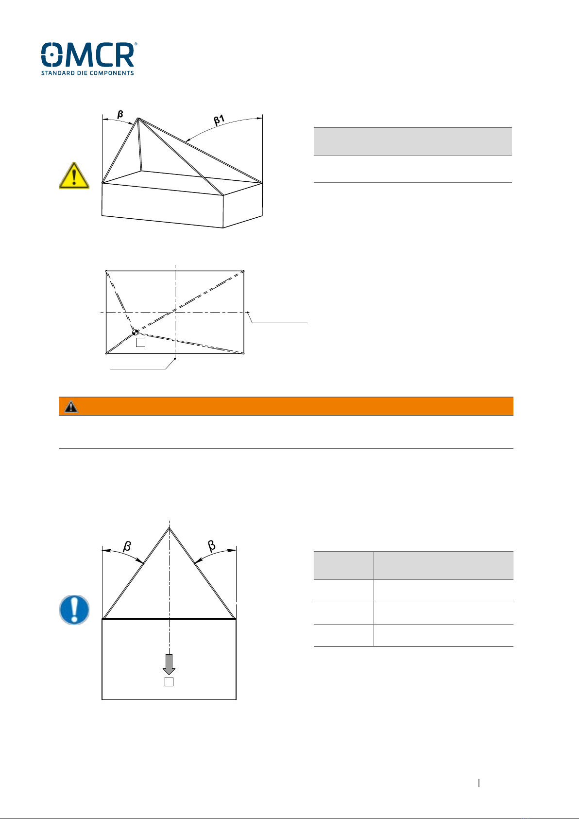
Refer to EN818-06 norm to define symmetric and asymmetric sling method: for asymmetric sling, the whole load
should be supported by only two rope/chain wings.
NOTE
Each lifting, handling or overturning operations must be executed by qualified and instructed
worker; the lifting, handling or turnover’ officers must use individual guard equipment.
WARNING
3.1
Before each lifting / handling / overturning officers have to choose the most suitable sling to
ensure a safe suspension with a correct load balance. A wrong sling method can modify the
real capacity load of the ropes and lifting accessories. In the following table you can verify
the reduction of the nominal capacity load related to the sling angles in order to preserve
the minimum safety factor.
WARNING
3.2
ANGLE REDUCTION FACTOR OF THE
NOMINAL CAPACITY LOAD
0°≤β≤40° 1
40°<β≤50° 0.6
50°<β≤60° 0.4
SYMMETRIC SLING EXAMPLE
(RECOMMENDED CONDITION)
3.2.1 - LIFTING
G
G= Die load center
β= Rope angle from vertical
NOTE: lifting with β>60° is not provided
DIE AXIS
DIE AXIS
5. Use and maintenance manual B01.11 S. Maurizio C.se - 18/12/2020 www.omcr.it
G
G= Die load center
β= Minimum rope angle from vertical
β1 = Maximum rope angle from vertical
REDUCTION FACTOR OF THE NOMINAL
CAPACITY LOAD
0.5
ASYMMETRIC SLING EXAMPLE (β1>β)
WARNING
The missing respect of the prescriptions included in this manual may cause the accidental fall of the load.
3.2.2 - OVERTURNING
G
G= Die load center
β= Rope angle from vertical
ANGLE REDUCTION FACTOR OF THE
NOMINAL CAPACITY LOAD
0°≤β≤40° 0.6
40°<β≤50° 0.5
50°<β≤60° 0.4
SYMMETRIC SLING EXAMPLE
(RECOMMENDED CONDITION)
NOTE: overturning with β>60° is not provided.
DIE AXIS
DIE AXIS

6. Use and maintenance manual B01.11 S. Maurizio C.se - 18/12/2020 www.omcr.it
WARNING
The missing respect of the prescriptions included in this manual may cause the accidental fall of the load.
G
ANGLE REDUCTION FACTOR OF THE
NOMINAL CAPACITY LOAD
β<15°
β>40°
β1-β>15°
0.5
ASYMMETRIC SLING EXAMPLE
(β1>β)
G= Die load center
β= Minimum rope angle from vertical
β1 = Maximum rope angle from vertical
The die overturning is allowed only parallel with lifting bracket axis.
WARNING
3.2.3

7. Use and maintenance manual B01.11 S. Maurizio C.se - 18/12/2020 www.omcr.it
OMCR CODE NR. SCREWS SCREWS DIN
912 CL. 8.8 CLAMPING COUPLE
[Nm]
B01.11.20 2 M10x30 50,01
B01.11.25 2 M12x40 87,28
B01.11.32 2 M16x45 210,8
B01.11.40 2 M20x60 411,9
B01.11.50 2 M24x70 711
B01.11.63 4 M20x90 411,9
The missing respect of the prescriptions included in this manual may cause the accidental fall of the load.
WARNING
During the operation of lifting / handling / overturning of the die, please respect the maxim
dimensions of the ropes written in the table to guarantee the correct operation of the stop
rope safety system (see Pic.1)
WARNING
3.3
OMCR CODE Ømax
B01.11.20 8
B01.11.25 10
B01.11.32 10
B01.11.40 12
B01.11.50 14
B01.11.63 16
Before each lifting / handling / overturning of the die, check that the chosen sling system
(rope/chain, hook, etc.) doesn’t present any defect or deformation to make it unsafe;
otherwise replace immediately the damaged parts.
WARNING
3.4
Pic.1
WARNING
3.5
At the moment of the use, check the correct screws clamping and the use of screws with the
required lengths; in the following table are written down screws and clamping couples for the
fixing of the lifting brackets; it is recommended to use threadlocker LOCTITE 243 or lock
washers.Absolutely ensure a minimum screws clamping of 1 x Ø screw. Lifting brackets
should be mounted on steel plates (minimun quality Fe510, S355).

8. Use and maintenance manual B01.11 S. Maurizio C.se - 18/12/2020 www.omcr.it
PRODUCT CODE
WORK ORDER NUMBER
MAXIMUM CAPACITY LOAD
CE MARK
CONSTRUCTOR
Pic.3
At the moment of use, check that the fixing-seats of the bracket have been carried out
(see Pic.2).
WARNING
3.6
The missing respect of the prescriptions included in this manual may cause the accidental fall of the load.
WARNING
OMCR CODE H [mm]
B01.11.20 8
B01.11.25 10
B01.11.32 10
B01.11.40 12
B01.11.50 14
B01.11.63 16
Pic.2
Before each lifting / handling / turnover check that the lifting brackets capacity load is in
compliance with the die weight; the maximum capacity load, the work order number, the
constructor label and the EC conformity mark are indelibly marked on the lifting brackets
(see Pic.3).
WARNING
3.7

9. Use and maintenance manual B01.11 S. Maurizio C.se - 18/12/2020 www.omcr.it
In case of lifting and handling, the lifting bracket capacity load should be at least 1/2 of the whole die weight.
(upper half-die + lower half-die).
Example: Die weight 10.000 kg - minimum lifting bracket capacity load: 10.000 / 2 = 5.000 kg
In case of half-die overturning the lifting bracket capacity load should be at least 1/2 of the half-die weight.
Example: Half-die weight 5.000 kg - minimum lifting bracket capacity load: 5.000 / 2 = 2.500 kg
Before each lifting / handling / overturning of the die be sure that:
the ropes are secured in correct way;
the ropes are not in contact with cutting edge;
the ropes are not hooked to the die corners.
WARNING
3.9
To prevent the sling accidental extraction, don’t make lifting / handling / overturning with
sling angle bigger than 90° from the horizontal level (see Pic.4).
WARNING
3.8
Pic.4
50°
<50°

10. Use and maintenance manual B01.11 S. Maurizio C.se - 18/12/2020 www.omcr.it
4. HANDLING AND STORAGE
OMCR CODE WEIGHT (kg)
B01.11.20 0,4
B01.11.25 0,9
B01.11.32 1,3
B01.11.40 2,2
B01.11.50 3,6
B01.11.63 8
4.2 If not used the lifting brackets must be stored far from wet and preserved from oxidation by appling
protective oil.
In the following table are written OMCR B01.11. lifting brackets weights; the lifting
brackets must be handled in compliance with the current norms concerning the
movement by hand of the loads.
WARNING
4.1
At the moment of the assembling, carefully clean the contact surfaces between lifting
brackets and steel plates.
The presence of oil or dirt on the contact surface between the lifting bracket and the mold
holder plate may compromise the correct functioning of the lifting bracket
WARNING
4.2.1
Don’t stand or transit nearby the load during lifting, handling or overturning operations (see
Pic.5). In case of accidental release of the load there may be risks of injury.
WARNING
3.10
Pic.5
Other manuals for VDI3366
1
This manual suits for next models
7
Table of contents
Languages:
Other OMCR TV Mount manuals