OHAUS DEFENDER T72XW User manual

T72XW OPTIONS
- Ethernet Interface
- USB with IO
- COM2
Instruction Manual
T72XW OPCIONES
- Interfaz Ethernet
- USB con IO
- COM2
Manual de instrucciones
T72XW OPTIONS
- Interface Ethernet
- USB avec e/s
- COM2
Mode d'emploi
T72XW OPTIONEN
- Ethernet Interface
- USB mit IO
- COM2
Bedienungsanleitung
T72XW OPZIONI
- Interfaccia Ethernet
- USB con IO
- COM2
Manuale di istruzioni


T72XW Options Manual EN-1
INTRODUCTION
This manual provides installation instructions for the T72XW Terminal Options. Please read these
procedures thoroughly before beginning installation.
OPENING THE ENCLOSURE
The front panel of the harsh enclosure T72XW terminal is locked in place by six spring clips attached
to the body of the enclosure. To access the terminal’s PCB to install options, connect internal wiring
and set switches, separate the front panel from the enclosure as follows:
Insert the tip of a flat-blade screwdriver into one of the two slots located on the bottom of the front
panel assembly (see Figure 1-1). While squeezing the front panel and enclosure together, gently push
the screwdriver in toward the enclosure. A “pop” sound is made when the cover clip is released.
Figure 1-1: Opening the Harsh Enclosure
Repeat Step 1 for the other slot.
After releasing the two clips securing the bottom of the front panel, move the panel to each side to
disengage the side clips, then lift the bottom of the front panel firmly up and out (Figure 1-2, 1) until it
completely clears the top edge of the bottom enclosure.
Squeeze the top of the front panel to the enclosure along the top edge slightly and push upward
(Figure 1-2, 2) to unsnap the top two clips, then lift the cover to clear the two top clips. The cover will
swing down, hinged by two wire cables at the bottom.
Figure 1-2: Removing the Cover
1
2
EN-2 T72XW Options Manual
MAIN BOARD WIRING CONNECTIONS
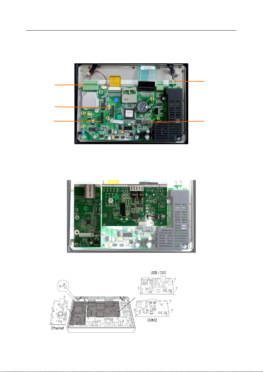
Once the T72XW terminal harsh enclosure is open, connections can be made to the terminal strips on
the main board, as shown in Figure 1-3.
Figure 1-3: T72XW Main Board Connections, AC Model
Figure 1-4 shows the two option locations on the main board, where the boards mount on the
connectors indicated in Figure 1-3. Figure 1-5 shows the mounting position for each option.
Connections for each option are described in the following sections.
Figure 1-4: Option Board Locations
Figure 1-5: Option Board Locations
DIP switches
AC power
connector
Load cell
connector
Option 1
connector
Option 2
connector

T72XW Options Manual EN-3
WIRING CONNECTIONS FOR OPTIONS
ETHERNET CONNECTIONS
The Ethernet option board (Figure 1-6) is positioned in position 2 on the main board (Figure 1-3). This
port provides a 10 Base-T connection (10 Mb) connection for Ethernet.
The Ethernet connection is made via a standard RJ45 connector (indicated in Figure 1-6) on the
option board
Figure 1-6: Ethernet Connection Option Board
Important: When installing the Ethernet option, adhere the Ethernet label from the kit to the enclosure
near the Ethernet connector.
COM2 CONNECTIONS
The COM2 option board (Figure 1-7) is positioned in option position 1 on the Main board (Figure 1-3).
This option board provides a single serial port labeled COM2.
Figure 1-7: COM2 Option Board
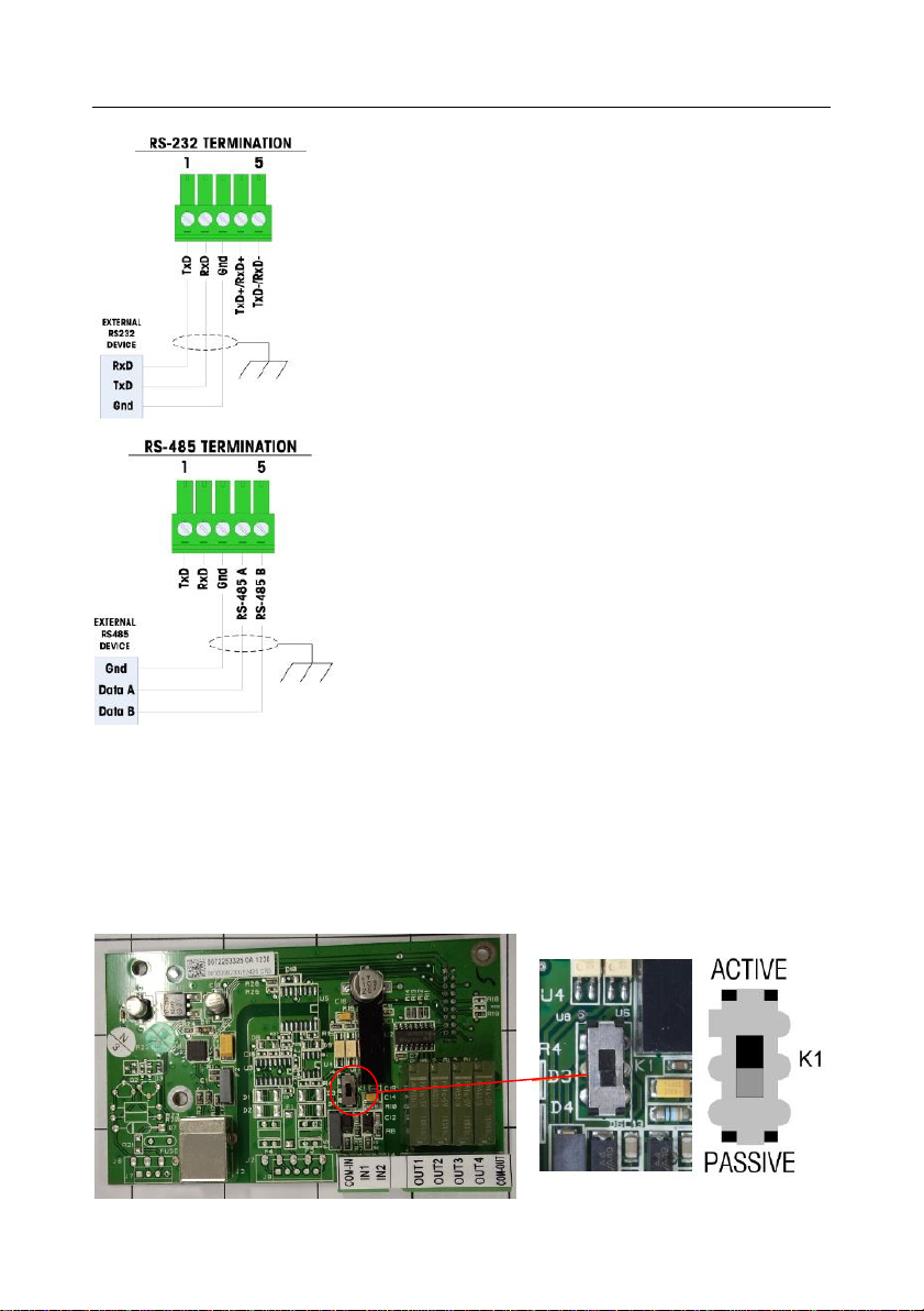
The COM2 port provides RS-232 and RS-485 connections. There is a setup
parameter that must be selected to match the hardware connection used. This
parameter controls how the transmit and receive lines are controlled. See Figure
1-8 and Figure 1-9 for connection details.
Terminal
Signal
TxD
Transmit RS-232
RxD
Receive RS-232
Gnd
Logic Ground
RS-485 A
RS-485 data A
RS-485 B
RS-485 data B
Figure 1-8: COM2 Port Signals
RJ45
connector
EN-4 T72XW Options Manual
Figure 1-9: Sample COM2 Connections
USB WITH DISCRETE I/O CONNECTIONS
The USB I/O option board (Figure 1-10) is positioned in option position 1 on the Main board (Figure 1-
3). This option board provides a single USB type B connector port with two isolated inputs and four
dry-contact, normally open relay outputs. The inputs can be selected as either active or passive based
on the position of the slide switch on the board. The connectors and switch are visible in Figure 1-10.
Figure 1-10: USB/DIO Option Board
Notes
1. Use only shielded cable
2. Maximum cable length: 1000 feet (304 meters)
3. Wire size: 18 AWG (0.832 mm2) Maximum
24 AWG (0.205 mm2) Maximum
Notes
1. Use only shielded cable
2. Maximum cable length: 50 feet (15 meters)
3. Wire size: 18 AWG (0.832 mm2) Maximum
24 AWG (0.205 mm2) Maximum

T72XW Options Manual EN-5
Active Input
Selecting the inputs as active (Figure 1-10) enables connection of switches or
other simple devices to trigger an input. No voltage is supplied by the external
simple device.
Passive Input
Selecting the inputs as passive (Figure 1-10) enables other devices such as PLCs
to provide the trigger voltage (typically 12 VDC or 24 VDC, maximum 30 VDC) to
turn the T72XW inputs “on”.
CLOSING THE ENCLOSURE
After all work has been completed inside the terminal, the enclosure must be
snapped shut properly to maintain its environmental integrity.
To properly close the terminal, follow these steps:
1. Position the front cover over the rear housing then gently press it down into
place.
2. Press down firmly in each of the four corners of the front cover in sequence
until each corner clip snaps audibly snaps into place.
3. It is very important that each of the 4 corner clips have snapped into place.
When pressing down on the cover during installation, listen for the “click”
sound of each clip engaging.
COMPLIANCE
Disposal
In conformance with the European Directive 2002/96 EC on Waste Electrical and
Electronic Equipment (WEEE) this device may not be disposed of in domestic waste.
This also applies to countries outside the EU, per their specific requirements.
Please dispose of this product in accordance with local regulations at the collecting
point specified for electrical and electronic equipment. If you have any questions,
please contact the responsible authority or the distributor from which you purchased
this device.
Should this device be passed on to other parties (for private or professional use), the
content of this regulation must also be related.
For disposal instructions in Europe, refer to www.ohaus.com/weee.
Thank you for your contribution to environmental protection.


T72XW Opciones ES-1
INTRODUCTION
Este capítulo proporciona instrucciones de instalació n para el terminal T72XW opciones . Lea estos
procedimientos detenidamente antes de comenzar la instalació n.
Apertura de la caja
El panel frontal de la caja para ambientes adversos del terminal T72XW está fijado mediante seis
sujetadores de resorte fijos en el cuerpo de la caja. Para tener acceso a la PBC del terminal para
instalació n de opciones, conectar el cableado interno y colocar interruptores, separe el panel frontal
de la caja como sigue:
Inserte la punta de un destornillador plano en una de las dos ranuras que se encuentran en la parte
inferior del ensamble del panel frontal (vea la Figura 1-1). Mientras junta el panel frontal y la caja,
presione suavemente el destornillador hacia la caja. Se escucha un sonido “pop” cuando se suelta la
pinza de la tapa.
Figura 1-1: Apertura de la caja para ambientes adversos
Repita el paso 1 en la otra ranura.
Despué s de soltar las dos pinzas que aseguran la parte inferior del panel frontal, mueva el panel
hacia cada lado para desconectar las pinzas laterales y luego levante la parte inferior del panel frontal
con firmeza hacia arriba y afuera (Figura 1-2, 1) hasta que salga completamente del borde superior
de la parte inferior de la caja.
Presione la parte superior del panel frontal hacia la caja ligeramente a lo largo del borde superior y
empuje hacia arriba (Figura 1-2, 2) para soltar las dos pinzas superiores, y entonces levante para
destrabar las dos pinzas superiores. La cubierta bajará sostenida por dos cables de alambre en la
parte inferior.

ES-2 T72XW Opciones
Figura 1-2: Retiro de la cubierta
Conexiones para cables de la tarjeta principal
Una vez que la caja para ambientes adversos del terminal T72XW esté abierta, las conexiones
pueden hacerse en las tablillas de terminales en la tarjeta principal como se muestra en la Figura 1-3.
Figura 1-3: Conexiones de la tarjeta principal del T72XW, modelo para corriente alterna
La Figura 1-4 muestra las dos ubicaciones opcionales en la tarjeta principal, donde las tarjetas se
montan en los conectores indicados en la Figura 1-3 La Figura 1-5 muestra la posició n de montaje
para cada opció n. Las secciones siguientes describen conexiones para cada una de las opciones.
Figura 1-4: Ubicaciones de las tarjetas opcionales
Interruptores
DIP
Conector
de corriente
alterna
Conector de
la cé lula de
carga
Conector
opció n 1
Conector
opció n 2
1
2
Table of contents
Languages:


