OBO Bettermann EÜK VK Series User manual
Mounting instructions
EÜK screed-covered duct system

EÜK screed-covered duct system
Mounting instructions
© 2023 OBO Bettermann Holding GmbH & Co. KG
Table of contents

EN | 3
EÜK mounting instructions
Table of contents
Table of contents
1 About these instructions 5
1.1 Target group 5
1.2 Relevance of these instructions 5
1.3 Types of warning information 5
1.4 Basic standards and regulations 5
1.5 Applicable documents 6
2 Intended use 6
3 Safety 6
3.1 General safety information 6
3.2 Personal protective equipment 6
4 System overview 7
4.1 System description 7
4.2 Installation principle 8
4.2.1 Screed types 8
4.3 Required tools 9
5 Preparations for mounting 9
5.1 Calculation of the duct lengths 9
5.2 Preparing for installation 10
6 Mounting underfloor junction boxes/underfloor device
sockets 12
7 Mounting the underfloor duct 15
8 Mounting the connection shackle and vertical bend 18
9 Mounting the height compensation set 22
10 Applying the screed 26
11 Completing mounting 29
11.1 Removing the mounting cover 29
11.2 Decoupling the underfloor junction box/underfloor device socket 30
11.3 Creating the earthing connection 32
11.4 Mounting the mounting lid 33
12 Applying the floor covering 33
13 Mounting the service outlets/cassettes 34
14 Performing the electrical installation 34
15 Maintaining the duct system 35

© 2023 OBO Bettermann Holding GmbH & Co. KG
Table of contents
16 Dismantling the duct system 35
17 Disposing of the duct system 35
17 Technical data 37
17.1 Underfloor junction box/underfloor device socket 37
17.2 Underfloor duct 37
17.3 Vertical bend 38
17.4 Connection shackle 38
17.5 Height compensation set 38
17.6 Mounting lid (for UZD/UGD) 39
EN | 5
EÜK mounting instructions
About these instructions
1 About these instructions
1.1 Target group
These instructions are intended for the following target groups:
– Trained electrical specialists charged with mounting the screed-cov-
ered duct system
– Electrical planners and engineers charged with the planning of under-
floor systems
Electrical work may only be carried out by specialist personnel with
electrical training.
1.2 Relevance of these instructions
– These instructions are based on the standards valid at the time of
compilation (April 2023).
– All the documents supplied with the product must be stored in an
easily accessible location, so as to be available when information is
required.
– We will not accept any warranty claims for damage caused through
non-observance of these instructions.
– Any images are intended merely as examples. Mounting results may
look different.
1.3 Types of warning information
Type of risk!
Shows a risky situation. If the safety instruction is not observed, then
serious or fatal injuries may occur.
Type of risk!
Shows a risky situation. If the safety instruction is not observed, then
medium or minor injuries may occur.
Type of risk!
Shows a risky situation. If the safety instruction is not observed, then
damage to the product may occur.
Note! Indicates important information or assistance.
1.4 Basic standards and regulations
– DIN EN 50085-1: Electrical installation trunking and duct systems for
electrical installations – Part 1: General requirements
– DIN EN 50085-2-2: Electrical installation duct systems for electrical
x WARNING
x CAUTION
CAUTION

Intended use
6 | EN OBO Bettermann
installations – Part 2-2: Particular requirements for cable trunking
systems and cable ducting systems intended for mounting underfloor,
flushfloor or onfloor.
– DIN VDE 0100: Low-voltage electrical installations
1.5 Applicable documents
– Declarations of conformity
– VDE symbol approvals
2 Intended use
The EÜK screen-covered duct system and the corresponding underfloor
device sockets/underfloor junction boxes are used for cable routing and
to install electrical resources (such as sockets, data technology and
multimedia connections). The duct system is completely made from
metal.
The EÜK screed-covered duct system is suitable for dry and wet-care
surfaces.
3 Safety
3.1 General safety information
Observe the following general safety information:
– Contact with electrical current can lead to an electric shock.
– Electrical work may only be carried out by specialist personnel with
electrical training.
– Before the screed work, seal all the openings so that no screed can
ingress.
3.2 Personal protective equipment
List of personal protective equipment to be used:
Use hand protection
Wear safety shoes
Wear eye protection
k
c
a
EN | 7
EÜK mounting instructions
System overview
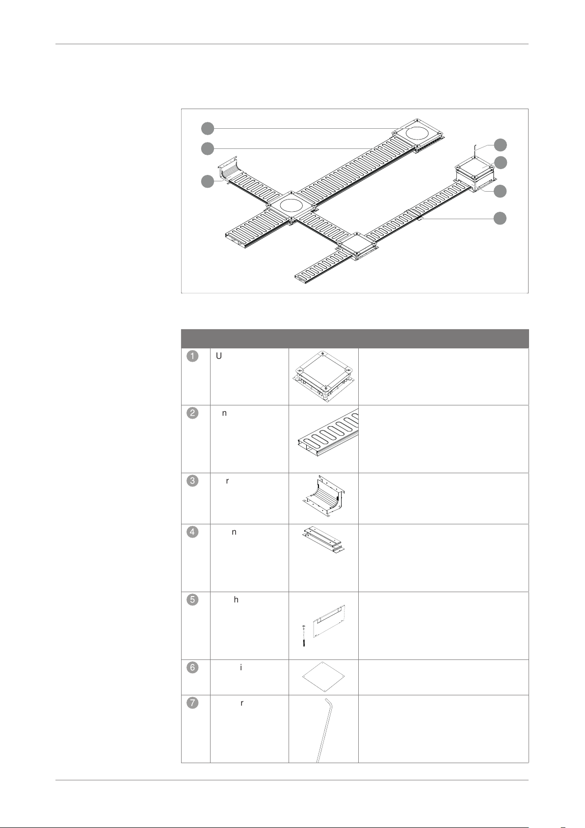
4 System overview
4.1 System description
Fig. 1:
1
2
3
4
5
6
7
Overview of system components
No. Product name Figure Function
1
Underfloor
junction box/
underfloor device
socket
Underfloor junction boxes/underfloor
device sockets with adjustable installation
opening. The underfloor junction boxes/
underfloor device sockets are available for
different floor heights.
2
Underfloor duct 2-piece underfloor duct (2- or 3-compart-
ment) for routing cables in screed-covered
underfloor systems, according to EN
50085-2-2. Removable and continuously
lockable duct cover. With separating
retainer in the duct base.
3
Vertical bend 2-part vertical bend for vertical direction
changes of screed-covered underfloor
ducts (wall connections, supply lines).
4
Connection
shackle
2-part connection shackle for conductive
mounting of screed-covered underfloor
ducts. The connection shackle snaps in to
the duct side walls. The electrical
conductivity is ensured via the snap-in
connection.
5
Height compensa-
tion set
If the floor structures differ from the
standard height adjustment heights, then
the underfloor junction boxes/underfloor
device sockets can be converted to the
required height using the height compen-
sation set.
6
Mounting protec-
tion cover
The mounting protection cover protects
the interior of the underfloor junction box/
underfloor device socket during mounting.
7
Quick release aid The quick release aid is required for
toolless height adjustment and subse-
quent decoupling of the socket top frame
from the socket base. The quick release
aids are available as an option. Item no.
7410160
System overview
8 | EN OBO Bettermann
Tab. 1: Overview of system components
The ducts are available in the widths 190, 250 and 350 mm and in the
heights 28, 38 and 48 mm, and are supplied ready for mounting with a
length of 2,000 mm.
To separate different voltage levels and stabilise the ducts, they have
asymmetrically/symmetrically arranged separating retainers in the
lengthwise direction. The duct width of 190 mm is equipped with a
separating retainer, the width 250 mm with one or two separating retain-
ers and the 350 mm duct width is always equipped with two separating
retainers.
Various cassettes and service outlets can be mounted in the screed-cov-
ered duct system using the underfloor junction boxes/underfloor device
sockets. They can be equipped with electrical resources. Sockets, data
and multimedia connections can be used with the Modul 45® series.
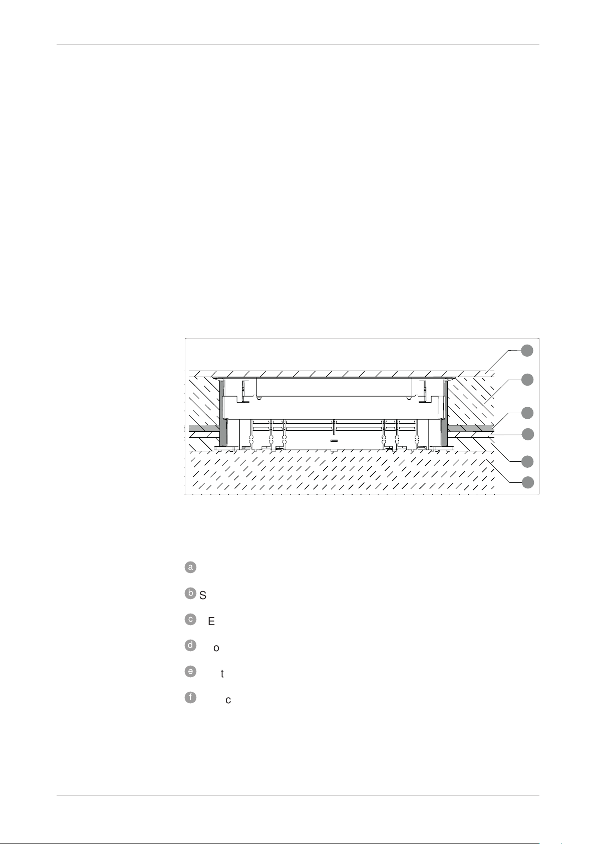
4.2 Installation principle
Fig. 2:
a
b
e
c
d
f
Installation principle of the screed-covered duct system
Components in the floor cross-section (floor structure/height conditions
may deviate depending on the floor planning):
a
Floor covering
b
Screed
c
PE film
d
Footfall sound
e
Heat insulation
f
Raw concrete
4.2.1 Screed types
The screed-covered duct system is always suitable for installation in all
screed types (according to DIN 18560).
EN | 9
EÜK mounting instructions
Preparations for mounting
Some screed types (magnesia screed, poured asphalt) require appropri-
ate preliminary work due to the properties of the screed materials.
4.3 Required tools
The following tools are required for the mounting of the screed-covered
duct system:
– OBO anchor
– OBO flattener
– Spirit level
– Side cutter
– Angle grinder
– Philips screwdriver
– Slotted screwdriver
– Adhesive tape, 50 mm wide
5 Preparations for mounting
5.1 Calculation of the duct lengths
During the planning and determination of the effective cable lengths of
the underfloor ducts
2
, the following deduction dimensions should be
taken into account.
Note! The deduction dimensions are always measured from duct stop to duct
stop (see detailed view in Fig. 3).
Article Type Deduction
dimension A
Vertical bend VK... 130 mm
Underfloor junction box/underfloor device
socket
UGD/UZD 250
UGD/UZD 350
280 mm
380 mm
Connection shackle VL... 8 mm

Preparations for mounting
10 | EN OBO Bettermann
Fig. 3:
a
A 380
A 280 A VK
UZD
UGD
250
UZD
UGD
350
A 380
10
Deduction dimensions
Legend
a Distance from socket centre to socket centre
A 280 Deduction dimension to UGD/UZD 250
A 380 Deduction dimension to UGD/UZD 350
A VK Deduction dimension, connection shackle
Example
a = 2,500 mm
A 250 = 280 mm
A 350 = 380 mm
A VL = 8 mm
Fig. 4: Formula for calculating the deduction dimensions
5.2 Preparing for installation
Risk of electric shock!
The duct system must be connected in a manner that is fully conductive!
The mounting of the screed-covered duct system takes place on the
raw floor, as the required electrical connection would not otherwise be
guaranteed.
Risk of damage!
Product damage to the height-adjustment units! During the construction
x CAUTION
AT T EN TI O N
This manual suits for next models
12
Table of contents
Popular Fan manuals by other brands

ELTA FANS
ELTA FANS H03VV-F installation guide

Hunter
Hunter 20714 Owner's guide and installation manual

Emerson
Emerson CARRERA VERANDA CF542ORB00 owner's manual

Hunter
Hunter Caraway Owner's guide and installation manual

Panasonic
Panasonic FV-15NLFS1 Service manual

Kompernass
Kompernass KH 1150 operating instructions


