(h) Individual Signaling. Momentary contacts
for individual signaling may be obtained by
removing the P0S14515 locking pin from the
key position which is to be converted and
making the wiring change given in Table E. The
momentary contact under the headset switch
may also be used for individual signaling (see
Fig. 5 or 6).
(i) Automatic Exclusion. This feature may be
obtained on one line by using an NE-10A
KTU (see Fig. 7). The feature provides
automatic cutoff of excluded stations whenever
the master station picks up the line associated
with the NE-lOA KTU.
(j) Selective Exclusion. This feature may be
obtained by using an NE-229B KTU (see
Fig. 8). The feature provides exclusion only if
the exclusion pushbutton on the key is
depressed momentarily. Any button on the key
may be converted for control by removing the
appropriate AG lead from terminal 40-45,
connecting this lead on terminal 30-32, and
removing the P0S 14515 locking pin. The lamp
in the exclusion button lights when the
exclusion circuit is in operation. Exclusion is
removed automatically when the call is either
placed on hold or terminated. The exclusion
circuit is compatible with COMPANION 3,
headset, or handset operation.
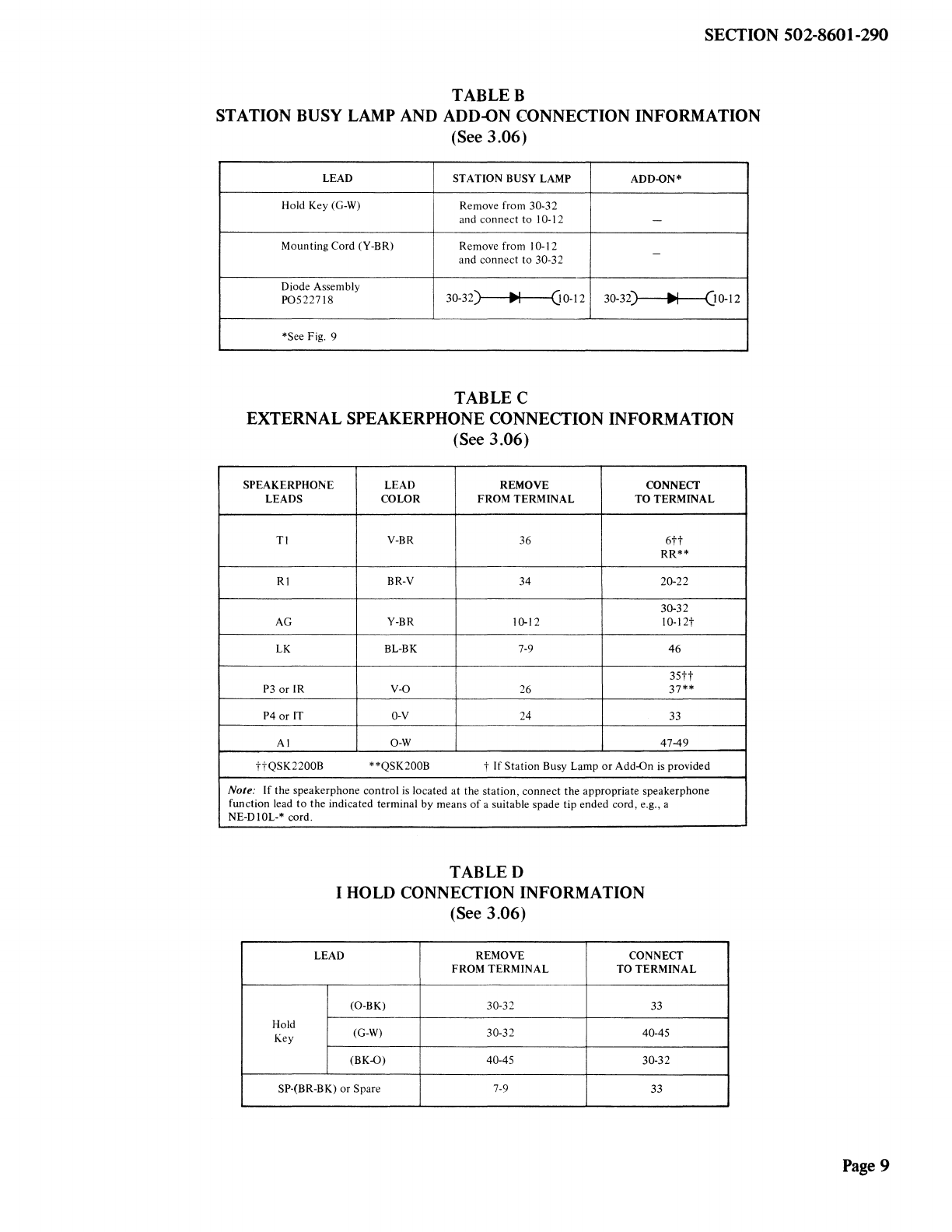
(k) Add-On Operation. The add-on feature may
be obtained on two lines by using an
NE-237B KTU (see Fig. 9 and Table B). Any
button may be used but must be made
nonlocking by removing the locking pin. The
lamp in the add-on button will light when the
add-on circuit is in use. The add-on circuit is
released by pressing the add-on button again or
hanging up the handset. The add-on circuit is
compatible with COMPANION 3, headset, or
handset operation.
(1) Ringer. The ringer feature is connected to
position 1 as shipped but may be connected
to another position or as a common ringer by
changing the wiring according to Table F and
connecting to the R-R 1 and B-B1 leads at the
key equipment.
SECTION502-8601-290
(m)Amplifier. An NE-241QB amplifier may be
required when using an NE-52 type or
equipment headset. Connection information is
given in Table G.
(n) Voice Station Coupler. A QCTIA voice
station coupler may be installed to provide
an automatic answering facility. Connection
information for this feature is given in Table H.
(o) Automatic Dialer. A variety of automatic
dialers are compatible with the LOGIC 10
sets. Connection information is given in Table I.
(p) Auxiliary Dial. An NE-1035B3QA station
dial may be used with the QSK200B
telephone set if computer input of DIGITONE
signals is required. Connection information is
given in Table J.
3. INSTALLATION
MOUNTING
3.01 For desk-top installation, the sets should be
placed in a convenient location on the desk
and connected to the appropriate connector cable.
3.02 For vertical surface installation, it is
necessary to use the accessory mounting
bracket and knurled thumb screw which are
supplied with each set. The installation should be
performed as follows.
(a) Attach the mounting bracket to the
mounting surface using two No. 8 screws or
similar mounting hardware. (The mounting
hardware must be obtained locally.)
(b) Place the telephone set on the mounting
bracket so that the shoulder rivets enter the
corresponding keyhole slots in the base of the
telephone set (Fig. 10).
(c) Move the telephone set to the left as far as
possible so that the lower front mounting
hole is in line with the corresponding threaded
hole in the telephone set base (Fig. 10).
Page3