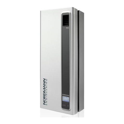
Nordmann NOVAP 3000 User manual

OPERATING INSTRUCTIONS
Steam Humidifier
2401917 EN 0801
Nordmann NOVAP 3000
NORDMANN
ENGINEERING
NORDMANN
ENGINEERING
Dampfluftbefeuchter econoVap

2
Introduction
List of contents
1. Installation
2. Water connections
3. Electrical connections
4. Putting into operation
5. Servicing and maintenance
6. Rectifying faults
7. Spare-parts list...............................................................................................................................................................................................................
8. List of options..................................................................................................................................................................................................................
9. Technical specifications..............................................................................................................................................................................................
You have purchased a NORDMANN steam humidifier which, provided
you observe the operating instructions, wi ensure fu y automatic
operation and re iab e, ow-maintenance service. Therefore, read these
operating instructions carefu y and pay particu ar attention to
the safety instructions and warnings.
Shou d you have any queries that go beyond the scope of these operating
instructions, p ease contact the company from which you purchased the
humidifier. As the manufacturers, we are, of course, a ways ready to be
of assistance, since we want a of our customers to be comp ete y satisfied
with our products.
1.1 Dimensions...................................................................................................................
1.2 Steam nozz e...............................................................................................................
1.3 Fitting the humidifier...............................................................................................
1.4 Fitting the steam-distribution pipe.....................................................................
1.5 Fitting the b owers....................................................................................................
1.6 Laying the steam hose..............................................................................................
1.7 Laying the condensate hose...................................................................................
2.1 Qua ity of the water..................................................................................................
2.2 Water intake and drainage.....................................................................................
3.1 Safety instructions.....................................................................................................
3.2 Contro vo tage..........................................................................................................
3.3 Heating vo tage..........................................................................................................
3.4 Proportiona adaptor (option)...............................................................................
4.1 How the humidifier works......................................................................................
4.2 The steam cy inder....................................................................................................
4.3 The SC-System (option)..........................................................................................
4.4 Putting the humidifier into operation................................................................
4.5 Automatic operation.................................................................................................
4.6 Setting the output imitation................................................................................
4.7 Indications of the two-co our LED.......................................................................
4.8 System and servicing indications..........................................................................
4.9 Remote indication.....................................................................................................
4.10 Safety functions.........................................................................................................
5.1 C eaning and rep acing the steam cy inder.......................................................
5.2 Drainage strainer in the steam cy inder.............................................................
5.3 Removing the e ectronics unit...............................................................................
5.4 Taking the humidifier out of operation..............................................................
5.5 Regu ar servicing........................................................................................................
6.1 The humidifier produces insufficient or no steam..........................................
4
7
7
8
10
11
12
13
13
14
15
15
16
17
18
18
20
20
20
21
21
22
22
22
23
24
24
24
25
26
26
27

3
Safety instructions
Very important!
Proper use
Alterations to the humidifier
Safety instructions
Please read and observe the operating instructions before fitting and
putting into operation.
The operating instructions shou d a ways be readi y avai ab e and kept
in the immediate vicinity of the humidifier.
A work must be done on y by persons who are fami iar with the product
and are sufficient y qua ified to perform the work.
The NOVAP 3000 steam humidifiers have been designed and constructed in
accordance with the atest techno ogy and the accepted safety regu ations.
However, if misused, the humidifier can present a danger to both the user
and third parties.
Apart from these safety instructions, you shou d observe a nationa and
oca regu ations.
The NOVAP 3000 steam humidifiers are intended so e y for indirect (via a
steam-distribution pipe in a venti ation duct) or direct (with either a
separate or a humidifier-mounted fan) humidification. Used in any other
way, or in a way that goes above and beyond the one described above, is
contrary to its intended usage. The manufacturer/supp ier cannot be he d
responsib e for any damage resu ting therefrom. The user sha bear the risk.
Without NORDMANN’s written approva , no a terations may be made to
the humidifier itse f, the components or the accessories.
The use of non-origina spare parts may ead to our refusa to accept
responsibi ity for any damage arising therefrom.
Whenever you see either of these signs,
particu ar care must be taken.
!

1.1 Dimensions
Dimensions of the NOVAP 3000 humidifiers
Fixing holes for type 64-90 kg/h (mm) Fixing holes for type 4-45 kg/h
4
BreiteTiefe
Höhe
1. Installation
Type Fig. mm mm mm Steam outlet Drainage Empty eight Full eight
ABC kgkg
41 390 585 230 1 x Ø 22 1 x Ø 22 11 14,5
81 390 585 230 1 x Ø 22 1 x Ø 22 12 18,5
15 1 470 645 305 1 x Ø 35 1 x Ø 22 17 32
23 1 470 645 305 1 x Ø 35 1 x Ø 22 18 33
32 1 525 715 360 1 x Ø 35 1 x Ø 22 28 53
45 1 525 715 360 2 x Ø 35 1 x Ø 22 29 54
64 2 975 730 385 2 x Ø 35 2 x Ø 22 62 112
90 2 975 730 385 4 x Ø 35 2 x Ø 22 64 114
Fig. 1
A
B
Befestigungsbohrungen
bei Geräte ab 15kg
550
300 300
930
Fig. 3 Fig. 4
4 ho es required
for humidifiers of
15 kg and above
3 ho es required
for humidifiers of
4 and 8 kg/h
Type A B
(mm) (mm)
4 - 8 kg 100 350
15-23 kg 180 410
32-45 kg 220 450
Tiefe Breite
Höhe
Fig. 2
C A
B
C A
B

5
Dimensions of the steam-distribution pipes
A
DC
B
ø8
3
138
116
105
116
100x100
Fig. 5
3
A
CD
M6
B
ø8
118
150
130
100
75
Fig. 6
Type/mm A B C D Fig. Art. no.
22-300 300 Ø 22 176 60 5 902 00 00
22-450 450 Ø 22 300 70 5 902 00 01
22-650 650 Ø 22 504 70 5 902 00 02
22-850 850 Ø 22 696 70 5 902 00 03
35-300 300 Ø 35 200 55 5 902 00 04
35-450 450 Ø 35 300 80 5 902 00 05
35-600 600 Ø 35 425 90 5 902 00 06
35-900 900 Ø 35 680 110 6 902 00 07
35-1200 1200 Ø 35 935 110 6 902 00 08
35-1500 1500 Ø 35 1275 110 6 902 00 09

Dimensions of the 4-23 kg/h steam blo ers
6
Fig. Type A B C D E F G H I
10 32 kg/h Ø 505 255 Ø M10 185 235 Ø 35 Ø 8
11 45 kg/h 200 505 255 350 M10 185 235 Ø 2 x 35 Ø 8
A
B
==
B
A
==
Fig. 7 Fig. 8 Fig. 9
BA
D
E
CGF
Fig. 10 Fig. 11
BC
AD
E
G
F
H
J
BC
AD
E
G
F
H
J
AB
D
C
E
FG
Type A B
4 - 8 kg 100 130
15-23 kg 180 240
Fig. Type A B C D E F G
mm mm mm mm mm mm mm
8 4 - 8 kg/h 230 205 220 145 165 Ø 22 Ø 8
9 15-23 kg/h 310 275 295 255 285 Ø 35 Ø 8
Dimensions of the Turbo 32
and 45 kg/h steam blo ers
Fixing holes for
4-23 kg/h steam blo ers
Dimensions of the 4-23 kg/h steam blo ers
Type 4-8 kg/h Type 15-23 kg/h

7
1.2 Steam nozzle
1.3 Fitting the humidifier
Positioning the humidifier
For sma er outputs of up to 4 kg/h, we offer a steam nozz e which can
be either fitted in air ducts, for instance, or used for direct room
humidification. The ru es for vaporisation ines ( ines needed to mix
the steam adequate y with air) must be observed here, too.
When the steam nozzle is employed, the length of the steam hose
should not exceed 1.5 metres.
All installation ork must be performed by trained personnel.
The customer himself is responsible for verifying their qualifications.
When fitting the humidifier, use on y the materia supp ied with the unit
and observe the various minimum distances that have been stipu ated.
To open the humidifier, turn the screw, using the correct screwdriver,
in an anti-c ockwise direction; the door to the water componentry or the
e ectrics then opens. To c ose, simp y push back into p ace (no screwing
down is necessary).
Ensure that there is sufficient room to perform servicing
and maintenance work, and that the unit is easi y accessib e.
To faci itate such work, mount the unit at eye eve .
We recommend that you fit the humidifier as near as
possib e to the steam-distribution pipes. The highest degree of
efficiency is attained when the humidifier is inked to the
steam-distribution pipe by the shortest possib e steam hose.
When insta ing the doub e units sizes 64 and 90 kg/h next to
each other, ensure that each drainage pipe is fed to a funne of
adequate size.
320
380
100 100 100
!
Fig. 12
Fig. 13

1.4 Fitting the steam-distribution pipe
Guidelines on fitting the steam-distribution pipes
Various fitting methods
All installation ork must be performed by trained personnel.
The customer himself is responsible for verifying their qualifications.
The visib e jet of steam issuing from the steam-distribution pipe
dissipates in the air on y after a certain distance. In order to prevent
condensation, a certain minimum distance to other parts of the
insta ation (such as venti ators, fi ters or pipe bends) must, therefore,
be maintained.
The steam-distribution pipes can be fitted either vertica y or horizonta y,
though you must ensure that the steam out ets are a ways vertica
to the air f ow. If fitted horizonta y, these apertures must be at the top.
An adhesive temp ate is supp ied with each steam-distribution pipe
to faci itate insta ation in, for instance, an air duct. NORDMANN’s
steam-distribution pipes are designed so that, if fitted straight, there
is automatica y a s ight dec ine of 3% which ensures that any condensate
f ows back again.
The ends (reverse side of mounting p ate) of the onger steam-distribution
pipes (types 35-900, 35-1200 and 35-1500) are equipped with an M6
fixing bo t.
!
2/31/3
min 300
8
Fig. 14
A
==
A
B
Fig. 16 A = min. 250
B = min. 150
Fig. 15 A = min. 200

9
Steam-distribution pipe fitted on suction side
Because of the under-pressure in the app iance or duct part,
condensate may be present in the steam-distribution pipe.
If there is an out et in the empty part (intended for the
distribution pipes) of the humidifier, the condensate can be b ed
off in the immediate vicinity. An a ternative method
of b eeding off the condensate can be seen in the diagram.
Fig. 22
Pressure-
compensation
hose
Stench trap
Type: Sperrfix 3
Tight-fitting
rubber bung
A
B
C
D
A
B
A
B
C
CC
A
BB
B
==
= B =
A
Fig. 19 A > 500
B = min. 100 Fig. 20 A > 500
B = min. 150
C = min. 0.15 A
Fig. 17 A > 300
B = 0.5 A Fig. 18 A > 350
B = min. 150
C = 0.3 A
D = min. 100
Fig. 21 A = min. 175
B = min. 100

1.5 Fitting the blo ers
Minimum distances for steam blo ers of type 4-23 kg/h
Minimum distances for steam blo ers of type 32-45 kg/h
Technical specifications for steam blo ers
All installation ork must be performed by trained personnel.
The customer himself is responsible for verifying their qualifications.
The steam b ower for distributing the steam in the room can be fitted
either direct y onto the humidifier itse f (excepting types 32, 45, 64 and
90 kg) or onto a wa .
For the humidifier to work best, correct steam distribution is essentia .
For this reason, you must observe the minimum distances when insta ing
the equipment.
B
A
10
!
Fig. 23
Fig. 25Fig. 24
Max. steam Air volume Po er Nominal Weight Steam pipe Condensate Noise
output m3/h supply rating kg H pipe G level (1m)
4 kg/h-8 kg/h 110 200/240 V 25 W 5 Ø 22 mm Ø 8 mm 46 dB (A)
15 kg/h-23 kg/h 650 50/60 Hz 170 W 15 Ø 35 mm Ø 8 mm 54 dB (A)
32 kg/h 800 220/240 V 110 W 8 Ø 35 mm Ø 8 mm 72 dB (A)
45 kg/h 800 50/60 Hz 110 W 8 2 x Ø 35 mm Ø 8 mm 72 dB (A)
450 mm
min.
15 m
Type 32: min. 1500 mm
Type 45: min. 2000 mm
450 mm
Type
A B
min. min.
4 kg 600 mm 3 m
8 kg 900 mm 5 m
15 kg 1000 mm 7 m
23 kg 1000 mm 10 m
Table of contents
Other Nordmann Humidifier manuals