LCD 36x24 Logic Boards User Manual G.docx
www.nkkswitches.com • engineering@nkkswitches.com
LCD 36x24 Logic Boards User Manual
7850 East Gelding Drive • Scottsdale, AZ 85260-3420
4. How to control the Logic Board mounted LCD64x32 switches
If you are using NKK controllers, you can skip this section. This section cover detail on how to control
LCD 64x32s mounted on the Logic Boards.
Please note the controller with the same port can control the LCD36x24. If you want the same design
have capability to control both type of the LCDs Please check the LCD36x24 Logic Board user manual
as some of indicated ground in below table need to be changed to LCD36x24 Logic Boards requirement.
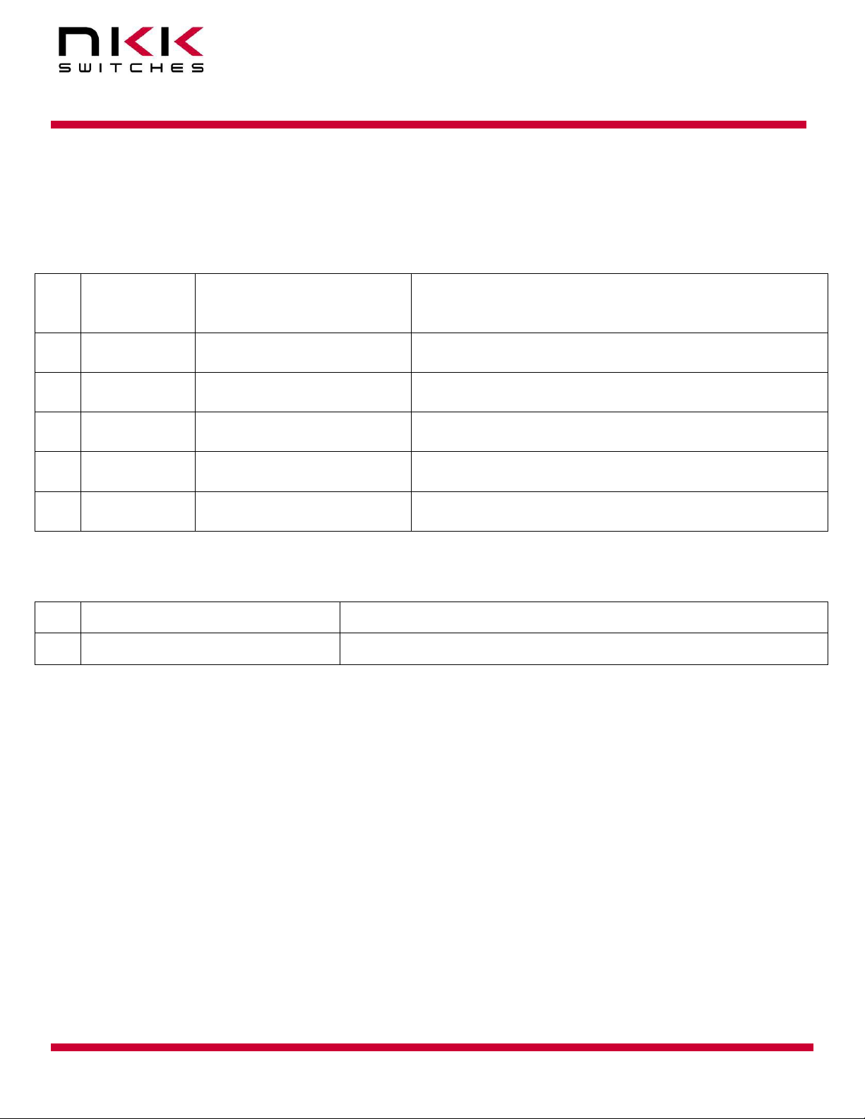
J1 of the first
Logic Board
Microcontroller pin (output)
Microcontroller pin (output)
Microcontroller pin (output)
7V to 12V. Closer to 7V is better
Microcontroller pin (output)
Microcontroller pin (output)
Microcontroller pin (output)
Microcontroller pin (output)
7V to 12V. Closer to 7V is better
Microcontroller pin (input) and 2K pull down to
GND
Clock and data can be connected to SPI/UART mode 0 or any pin of microcontroller. For SCP and Din,
LP, FLM signal please refer to the application note for LCD64x32 switches.
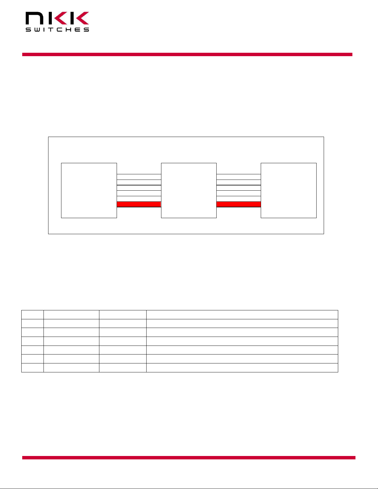
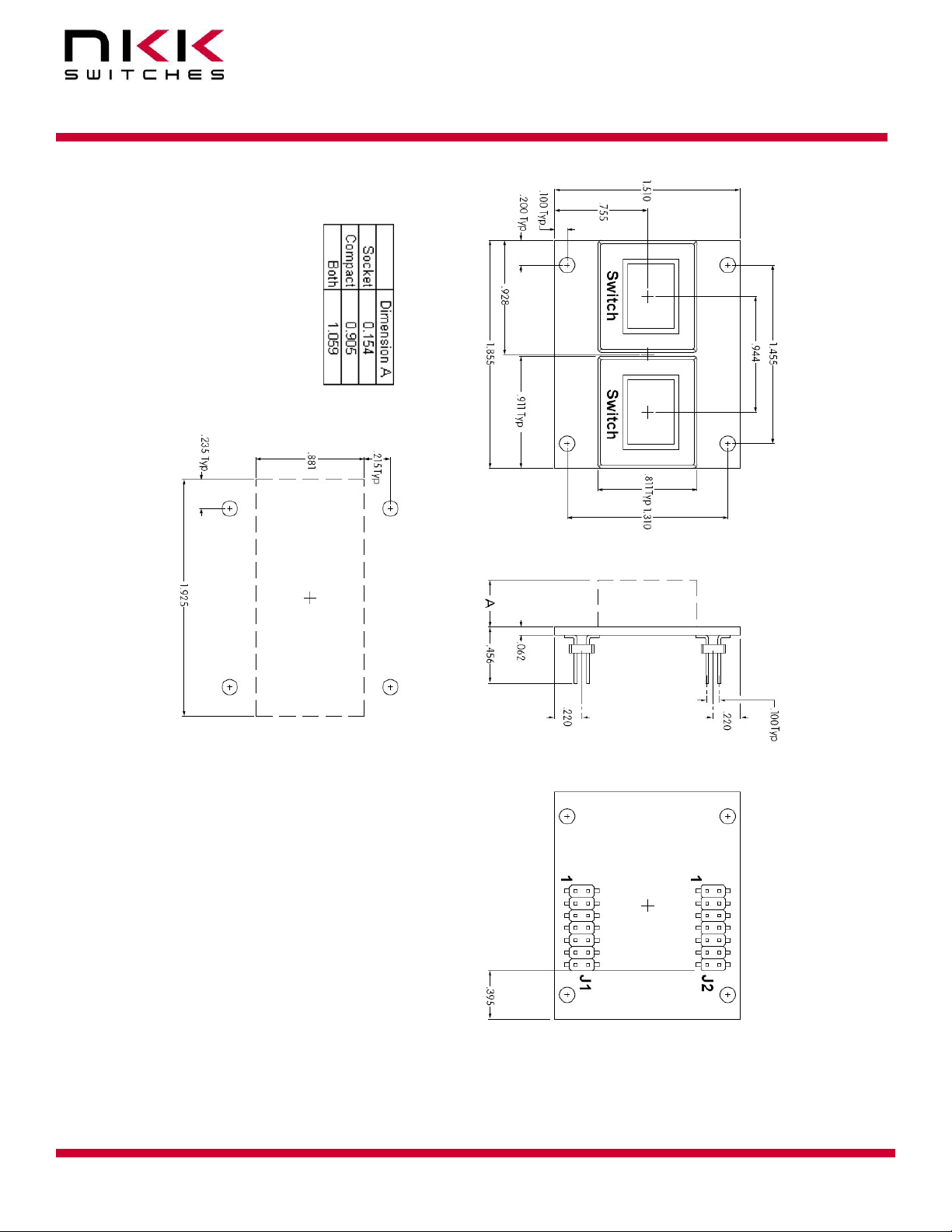
Switch Numbering
On each Logic Board the first switch is in the upper left-hand corner. Row by row with the last
switch in the lower right-hand corner. The switch numbering starts with switch one of the first
Logic Board. The first switch of the next Logic Board will be one higher than the last switch of the
previous Logic Board. Please note if a switch is missing the data does not get to any switch after
missing switch.
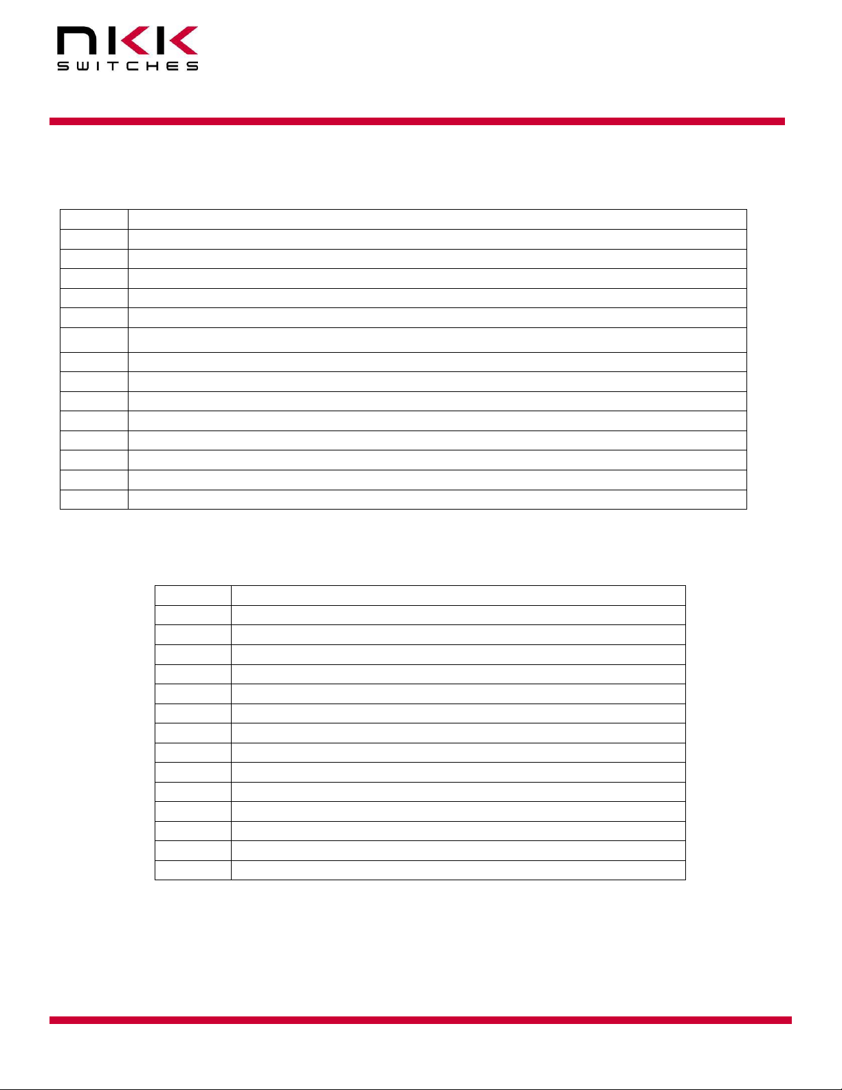
Controlling Backlighting
Four bits are used to control each switch backlight. The bits are shifted by SCP1 and Din1. The first
bit shifted is for red backlight, the second bit shifted is for green backlight, the third bit shifted is for
blue backlight, the fourth bit shifted is dummy bit. The last 4 bits shifted are for switch #1. Once the
all the backlight data are shifted The LP1 is taken high and then low. A bit =0 turn backlight ON and
a bit=1 Turn the backlight OFF. The LED Disable has to be Low for the backlight to go to effect. The
LED Disable can be used for brightness control disabling/Enabling the backlights.