NKE WiMo User manual
nke Instrumentation – 6 rue Gutenberg, ZI de Kerandré, 56700 Hennebont, France
WiMo / WiMo Plus
User Manual
Revision 1.3 (09.03.22)

WiMo / WiMo Plus Multiparameters Sondes
1
Table of contents
Table of contents
TABLE OF CONTENTS ........................................................................................................................................ 1
1INTRODUCTION........................................................................................................................................3
1.1 WIMO SPECIFICATIONS ............................................................................................................................... 3
1.2 WIMO PLUS SPECIFICATIONS........................................................................................................................ 4
1.3 PRESSURE SENSOR ...................................................................................................................................... 5
1.4 CLEANING DEVICE ....................................................................................................................................... 6
1.4.1 Installation on a WiMo probe............................................................................................................ 6
1.4.2 Installation on a WiMo Plus probe .................................................................................................... 7
2OPERATION.............................................................................................................................................. 7
2.1 SENSORS INSTALL........................................................................................................................................ 7
2.1.1 Install/Remove caps .......................................................................................................................... 8
2.1.2 Install/Remove sensors...................................................................................................................... 9
2.2 INSTALL/REMOVE GUARD .......................................................................................................................... 10
2.2.1 ISE sensor protection guard............................................................................................................. 11
2.3 SONDE ACTIVATION................................................................................................................................... 12
2.4 CONNECTION TO SONDE ............................................................................................................................ 12
2.4.1 PC .................................................................................................................................................... 13
2.4.2 Tablet .............................................................................................................................................. 13
2.4.3 Smartphone..................................................................................................................................... 14
3WEB INTERFACE..................................................................................................................................... 15
3.1 DASHBOARD MENU .................................................................................................................................. 16
3.1.1 General settings .............................................................................................................................. 16
3.1.2 Storage ............................................................................................................................................ 17
3.1.3 Network and communication.......................................................................................................... 17
3.1.4 Available parameters ...................................................................................................................... 18
3.1.5 Connected accessories..................................................................................................................... 18
3.1.6 Acquisition settings ......................................................................................................................... 18
3.2 MEASUREMENT FILES MENU ...................................................................................................................... 20
3.3 LIVE VIEW MENU ..................................................................................................................................... 21
3.4 ALARM MENU ......................................................................................................................................... 22
3.5 OPERATES SONDE IN FIVE STEPS................................................................................................................... 23
4MAINTENANCE ...................................................................................................................................... 24
4.1 ROUTINE MAINTENANCE............................................................................................................................ 24
4.1.1 O-rings service ................................................................................................................................. 24
4.1.2 Sensor port service .......................................................................................................................... 24
4.2 REPLACE BATTERIES................................................................................................................................... 25
5PRODUCT IDENTIFICATION .................................................................................................................... 26
6FILE FORMATS........................................................................................................................................ 27
6.1 TOPKAPI TXT2 FORMAT ............................................................................................................................ 27

WiMo / WiMo Plus Multiparameters Sondes
2
Table of contents
6.2 CSV FORMAT .......................................................................................................................................... 27
6.2.1 Datas ............................................................................................................................................... 28
6.2.2 settings ............................................................................................................................................ 28
7MANAGEMENT OF ALARM FILES............................................................................................................ 30
8OPERATION WITH THE WIMO MODEM.................................................................................................. 31
8.1FLOTTEUR WIMO 20 LITRES....................................................................................................................... 32
8.2 BOUEE COTIERE WIMO............................................................................................................................. 33
9RETURN A PRODUCT TO THE FACTORY .................................................................................................. 34

WiMo / WiMo Plus Multiparameters Sondes
3
Introduction
1Introduction
The WiMo multiparameter range, including the WiMo sonde (4 locations) and the WiMo Plus sonde
(7 locations), offers flexible and innovative solutions for water quality data collection. The sonde
have a native pressure sensor and temperature measurement and 4 to 7 additional sensors can be
added depending on the model. The end-user plugs directly the sensors to the sonde which are
automatically recognized (Plug and Play system). The sonde can also be connected to a transmission
module that will also be automatically detected.
Data can either be recorded in internal memory of the sonde or transmitted to a data collection
platform via the transmission modems. The sonde also operates in Modbus for real-time
measurement of the environment.
1.1 WiMo Specifications
The WiMo sonde has 4 universal locations where sensors or a cleaning system can be plugged. The
sonde is equipped with a pressure and temperature sensor.
It is powered by 6 Type D Alcaline batteries and is compliant with NiMH Type D rechargeable
batteries. The probe can, if necessary, receive an external power supply
A Wi-Fi link is used to setup the sonde and for file data transfer.
No dedicated software is needed to setup the WiMo. An Embedded WEB Server gives access to all
the sonde functionalities using an internet browser.
Number of locations
Operating environment
Maximum Depth
Communication
Weight
2,65 kg
Size
Diameter :
85 mm
Total length :
489 mm
Power supply
External 9 - 16 VDC
Internal 6 alkaline batteries type D or 6 NiMh rechargeable batteries type D
Temperature
Storage (no battery): -20°C à 70°C
Operating : - 2 à +50°C
WiMo Sonde Specifications
4
Fresh and sea water
250 m
WiFi / Modbus RTU

WiMo / WiMo Plus Multiparameters Sondes
4
Introduction
1.2 WiMo Plus Specifications
The WiMo Plus sonde has 7 universal locations where sensors can be plugged. The central location
can be used also for a wiper instead of sensor. The sonde is equipped with a pressure and
temperature sensor.
It is powered by 6 Type D Alcaline batteries and is compliant with NiMH Type D rechargeable
batteries.
A Wi-Fi link is used to setup the sonde and for file data transfer.
No dedicated software is needed to setup the WiMo. An Embedded WEB Server gives access to all
the sonde functionalities using an internet browser.
Universal
Location
Pressure
sensor
Handle
Guard
Wi-Fi Activation
6 pin connector

WiMo / WiMo Plus Multiparameters Sondes
5
Introduction
1.3 Pressure sensor
The pressure sensor is a piezoresitive sensor that measures absolute pressure. That’s means the
reference is vacuum. The sonde allows adding an offset to compensate the measured pressure with
the current atmospheric pressure in order to get a zeroing of the pressure sensor. However zero will
vary with changes in atmospheric pressure.
The sensor contains its own temperature measurement to make its compensation. Temperature
measurement is available in the WiMo and WiMo Plus sondes.
Number of locations
Operating environment
Maximum Depth
Communication
Weight
3,05 kg
Size
Diameter :
110 mm
Total length :
499 mm
WiFi / Modbus RTU
Power supply
External 9 - 16 VDC
Internal 6 alkaline batteries type D or 6 NiMh rechargeable batteries type D
Temperature
Storage (no battery): -20°C à 70°C
Operating : - 2 à +50°C
WiMo Plus Sonde Specifications
7
Fresh and sea water
250 m
Universal
Location
Pressure
sensor
Wiper/sensor
Location
Handle
Guard
Wi-Fi
Activation
6 pin connector
WiMo / WiMo Plus Multiparameters Sondes
6
Introduction
For depth information it is able in the sonde to activate a calculated depth parameter based on the
UNESCO equation.
Pressure measurement is done at the upper tap of the sonde. There is therefore a position offset
between the pressure measurement and the measurements made by the sensors. They don't have
all the same offset:
1.4 Cleaning device
The WiMo and WiMo Plus sondes allow a cleaning device on their location. This device is a smart
wiper. It self-configures according to the sensors that are connected to the sonde. It automatically
detects whether the sensors need or can be cleaned and adjusts its wipe accordingly.
You must take care to avoid having a sensor that should be wiped below the brush in the standby
position.
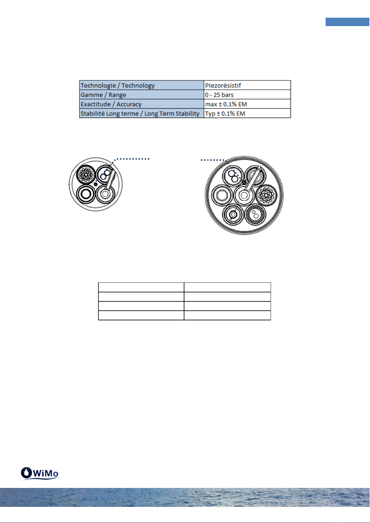
1.4.1 Installation on a WiMo probe
On version 4 slots (WiMo) the wiper can be placed on any location.
Conductivity 10,5 cm
Fluo Chla 12,3 cm
Dissolved oxygen 12,3 cm
Turbidity 12,3 cm
WiMo
WiMo Plus
Pressure
sensor
Pressure
sensor

WiMo / WiMo Plus Multiparameters Sondes
7
Operation
1.4.2 Installation on a WiMo Plus probe
On version 7 locations (WiMo Plus) the position of the wiper is unique and central.
2Operation
2.1 Sensors install
The WiMo and WiMo Plus sondes come with a cap on each sensor location. These caps ensure the
sonde is waterproof. When you remove a cap the sonde is no longer waterproof until you place a
sensor or a cap.
If the WiMo has been immersed in water you must dry the sonde properly before any dismantling.
The plug/unplugged operations of sensors or caps must be done head-down.
Standby position (cap or
non-wiped sensor)
Wiper location
WiMo Plus
Standby position (cap or
non-wiped sensor)
Wiper location
WiMo

WiMo / WiMo Plus Multiparameters Sondes
8
Operation
2.1.1 Install/Remove caps
Unscrew the locking sleeve in the anti-clockwise direction by hand or with the key tool provided. Pull
the cap to extract it. Place it on a clean surface and store it taking care not to damage the O-rings.
Before repositioning the cap check that the location in the sonde has no damage and no scratches.
Grease both O-rings of the cap with the grease provided and engage the cap in the location. Screw
the cap clockwise until the locking sleeve is in contact with the sonde head. Help with the key tool
provided if necessary.

WiMo / WiMo Plus Multiparameters Sondes
9
Operation
2.1.2 Install/Remove sensors
Unscrew the sensor locking sleeve in the anti-clockwise direction by hand or with the key tool
provided. Pull the sensor to extract it. Place it on a clean surface and store it taking care not to
damage the O-rings.
Before repositioning the sensor check that the location in the sonde has no damage and no
scratches. Grease the two sensor O-rings with the supplied grease and engage it in the location by
making the coded pin coincide with the host hole in the sonde. Take care to the sensor's centering in
its location. Move the sensor slightly from right to left to check that the pin is in front of its
receptacle before starting to screw. Be careful not to damage the threads of the sonde. Any
deterioration of the threads is not covered by the warranty.
Other manuals for WiMo
2
This manual suits for next models
1
Table of contents
Other NKE Marine Equipment manuals

NKE
NKE Pad Display Instruction Manual

NKE
NKE GYROPILOT 3 User manual

NKE
NKE 90-60-495 User manual

NKE
NKE CARBOWIND HR Instruction Manual

NKE
NKE HR Masthead unit Instruction Manual

NKE
NKE NMEA 90-60-360 Instruction Manual

NKE
NKE PROCESSOR HR User manual

NKE
NKE 90-60-398 User manual

NKE
NKE MULTIDISPLAY User manual
Popular Marine Equipment manuals by other brands


Clarion
Clarion GR10BT Owner's manual & installation manual

Raymarine
Raymarine Maxiview ST80 Owner's handbook

GUIDANCE MARINE
GUIDANCE MARINE 20- Series Installer's guide

Raymarine
Raymarine ST60 Tridata Owner's handbook

olympia electronics
olympia electronics ΒS-531/1/MAR quick start guide

Sonic
Sonic 2024 Operation manual