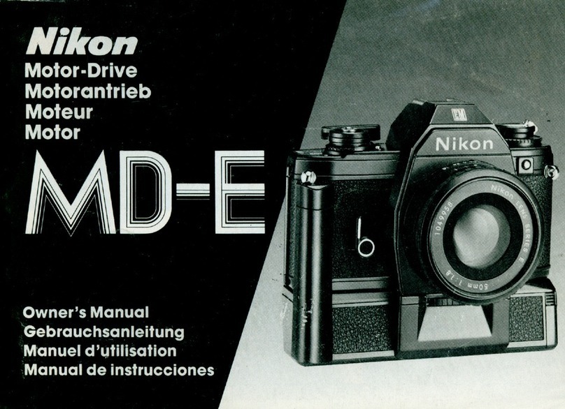
Nikon D100 VBA10201 Operating instructions

作成承認印 配布許可印
VBA10201-R.3577.A
VBA10201
Copyrigh c2002 by Nikon Corporation.
All Rights Reserved.
無断転載を禁ず
!!
Printed in Japan July 2002
Recycled paper
再生紙を使用しています
REPAIR MANUAL

VBA10201-R.3577.A
- M1 ・ -
Specications
ITEM CONTENTS
Type Single-lens reex digital camera with interchangeable lenses
Effective pixels 6.1 million
CCD 23.7 x 15.6 mm, 12-bit RGB CCD
Total pixels: 6.31 million
Image size (pixels) • 3008 x 2000 (Large)
• 1504 x 1000 (Small)
• 2240 x 1488 (Medium)
Lens mount Nikon F mount (with AF coupling and AF contacts)
COMPATIBLE LENSES
Type G or D AF Nikkor All functions supported
PC Micro Nikkor 85
mm F2.8D
All functions except autofocus supported
Other AF Nikkor All functions except 3D multi-sensor balanced ll ash
for digital SLR supported
AI-P Nikkor All functions except autofocus, matrix metering, and
3D multi-sensor balanced ll ash for digital SLR supported
Other Other lenses can be used in manual exposure mode;
electronic range nder can be used if lens has a maximum
aperture of f/5.6 or faster
Picture angle Equivalent in 35-mm format is approximately 1.5 times
lens focal length
Viewnder Optical xed pentaprism
Diopter adjustment –2.0 – +1.0 m–1
Eyepoint 20 mm (–1.0 m–1)
Focusing screen Type B BriteView clear matte screen Mark II with superimposed
focus brackets and On-Demand grid lines
Frame coverage Approximately 95% of lens (vertical and horizontal)
Approximate
magnication
0.8 x with 50-mm lens set to innity and –1.0 m–1
Reex mirror Quick-return
Lens aperture Instant return with depth-of-eld preview
Focus-area selection Can be selected from ve focus areas
Lens servo Instant single-servo AF (S), continuous servo AF (C),
manual (M); focus tracking automatically activated according
to subject status in single-servo and continuous-
servo AF
Autofocus TTL phase detection by means of Nikon Multi-CAM900
autofocus module with AF-assist illuminator (range
approximately 0.5 – 3 m/1´8˝–9´10˝)
Detection range –1 – +19 EV (ISO 100, room temperature)
AF-area mode Single-area AF, dynamic-area AF (supports closest-subject
priority)
Focus lock Focus can be locked by pressing shutter-release button
halfway (single-servo AF) or pressing AE-L/AF-L button

VBA10201-R.3577.A
- M2 ・ -
EXPOSURE
Metering Three-mode through-the-lens (TTL) exposure metering
Matrix 3D matrix metering supported with type G and D lenses;
matrix metering available with other lens types
Center-weighted Weight of 75% given to 8-mm circle in center of frame
Spot Meters 4-mm circle in center of frame; with CPU lens,
metered area linked to selected focus area
Range 0 – 21 EV (3D matrix or center-weighted metering)
3 – 21 EV (spot metering)
(ISO 100 equivalent,f/1.4 lens, 20°C/68°F)
Exposure meter coupling Combined CPU and AI
Exposure control Programmed auto with exible program; shutter-priority
auto; aperture-priority auto; manual; exposure compensation
(–5 – +5 EV in increments of 1/3 EV); auto
bracketing (2 or 3 exposures in steps of 1/3 or 1/2 EV)
Exposure lock Locked at detected value with AE-L/AF-L button
Shutter Combined electronic (CCD) and mechanical shutter
Speed 30 – 1/4000 in 1/3 EV steps, long time-exposure (bulb)
Sensitivity 200 – 1600 (ISO equivalent) in steps of 1/3 EV; auto gain to ISO 1600 equivalent
White balance TTL white balance control with white balance bracketing
Built-in Speedlight Pop-up Speedlight with button release
Guide number Guide number 12/39 (ISO 100, m/ft)
Illuminating angle Same as 20-mm lens
FLASH
Sync contact X-contact only; ash synchronization at up to 1/180 s
Flash control • Automatic balanced ll ash controlled by ve-segment TTL multi sensor with
single-component IC.
Supports 3D multi-sensor balanced ll ash for digital SLR (built in Speedlight or SB series
80DX/50DX/28DX with type G or D lens) and multi-sensor balanced ll ash for digital SLR
(built in Speedlight or SB series 80DX/50DX/28DX with other CPU Nikkor lens)
• Non-TTL auto
Flash sync modes Front-curtain sync (normal), red-eye reduction, red-eye reduction with slow sync, slow sync,
rear curtain
Flash-ready light Lights when built-in Speedlight or SB-series 80DX, 50DX, 28DX, 28, 27, or 22s is fully
charged; blinks for three seconds after ash is red at full output
Accessory shoe Standard ISO hot-shoe contact with safety lock

VBA10201-R.3577.A
- M3 ・ -
STORAGE
Media Type I and II CompactFlash™ cards; Microdrives®
File system Compliant with Design Rule for Camera File Systems
(DCF) and Digital Print Order Format (DPOF)
Compression • Compressed NEF (raw): 12-bit lossless compression
• JPEG: JPEG baseline compliant
Self-timer Electronically controlled; duration 2– 20 s
Depth-of-eld preview
button
Lens aperture stopped down when button is pressed
Monitor 1.8˝, 120,000-dot, low temperature polysilicon TFT LCD with adjustable white LED backlight
and brightness adjustment
Video output Can be selected from NTSC and PAL
External interface USB
Tripod socket 1/4˝ (JIS)
Power source • One rechargeable Nikon EN-EL3 lithium-ion battery
• MB-D100 multi-function battery pack (available separately) with two rechargeable Nikon
EN-EL3 lithiumion batteries or six LR6 (AA) lithium or alkaline batteries
• EH-5 AC adapter (available separately)
Approximate dimensions
(W x H x D)
144 x 116 x 80.5 mm (5.7˝ x 4.6˝ x 3.2˝)
Approximate weight 700 g (25 oz) without battery or memory card
OPERATING
ENVIRONMENT
Temperature 0 – 40°C (32– 104°F)
Humidity Less than 85% (no condensation)
* Unless otherwise stated, all gures are for a camera with a fully-charged battery operating at an ambient temperature of
20 °C(68°F)

VBA10201-R.3577.A
- -
Disassembling
…………………………………………………………………………… D1
……………………………………………………………………… D1
…………………………………………………… D2
…………………………………………………………… D2
…………………………………………… D3
………………………………………… D3
………………………………………… D4
…………………………………………………………………… D4
………………………………………………………………… D5
…………………………………………… D6
……………………………………………………………… D6
……………………………………………………………… D7
…………………………………………………… D7
…………………………………………………………… D8
…………………………………………………………………… D8
………………………………………… D9
……………………………………… D9
……………………………………………………………… D10
……………………………………………………………………………… D10
…………………………………………… D11
…………………………… D11
…………………………………………………………… D12
………………………………… D13
…………………………………………… D14
Cautions
1. SEPARATION OF THE FRONT BODY FROM THE REAR BODY
Bottom Cover
Back Cover
1. Removal of Connection FPC
2. Removal of Screws
3. Discharging from Main Condenser
Memory Compression PCB Unit
1. Disconnection of FPCs from connector
2. Removal of Memory Compression PCB
CCD PCB Unit
DC/DC PCB Unit
Front Cover, Grip Cover and I/F Cover
Top Cover
1. Removal of Wires
2. Removal of Screws
3. Removal of wires and FPCs
Power Drive PCB Unit
Main Condenser
Separation of Front Body and Rear body
2. FRONT BODY
Shutter
1. Mirror-up, Removal of soldering bridges
2. Removal of Shutter
SQ FPC
Main FPC
1. Removal of FPC from the connector
2. Removal of pressure welding and soldering bridges
3. Removal of Main FPC
Prism Box Unit
1. Removal of Prism Box Unit from Front Body
2. Disassembling of the Prism Box Unit

VBA10201-R.3577.A
- -
……………………………………………………………………… D15
………………………………………………………… D16
…………………………………………………………………… D16
……………………………………………… D17
………………………………………………………… D17
……………………………………………………………………… D18
……………………………………………………………………… D19
…………………………………… D20
…………………………………………………………………… D21
AF Sensor Unit
TTL SPD Unit
Horizontal AF Lever Unit
Bayonet Mount
AM Switch Unit and AF Driving Unit
Aperture Control Base Plate
Mirror Holder
3. REAR BODY
I/F PCB Unit
CF PCB Unit
SB PCB Unit
Battery Contact and Small Parts in Rear Body
Bottom Plate Unit

VBA10201-R.3577.A
- D1 ・ -
Disassembling
Cautions:
① In disassembly and assembly, carry out the work by using the conductive mat (J5033) and list straps
(J5033-5) to protect the electric parts from static electricity.
②Before disassembling, remove the batteries or the AC power cord.
③When disassembling, remember the processed condition of lead wires and FPC, the setting positions and
kinds of screws, etc.
④ The low-pass lter of the image CCD PCB unit is liable to damage. Handle it very carefully.
⑤ In disassembly, a large assembly unit is sometimes removed. If such a large unit must be disassembled
furthermore, refer to the exploded drawings.
⑥ The chapters of disassembling and assembly do not mention the water proof sponge. When the part is
replaced, refer to the exploded drawings and set a waterproof sponge. For the setting position, refer to the
original part to be replaced.
⑦ The battery for backup is mounted on the DC/DC PCB. For replacing the battery for backup, accordingly,
disassemble the DC/DC PCB as well.
1. SEPARATION OF THE FRONT BODY FROM THE REAR BODY
Bottom Cover
#805
#662x6
#806
#664
Open the I/F cover.
WARNING
There are high voltege parts inside. Be careful of this electric shock,
when you remove the cover.
You must discharge the main condenser according to the instruction
of this repair manual before you remove the cover.
!

VBA10201-R.3577.A
- D2 ・ -
Back Cover
Disconnect the TFT PCB
connection FPC from the
slider.
#827
#821x2
#615x2
CF card eject button
2. Removal of Screws
• Remove 5 screws.
• Open the CF cover. Then remove the back cover as letting go the CF card eject button.
1. Removal of Connection FPC
WARNING
There are high voltege parts inside. Be careful of this electric shock,
when you remove the cover.
You must discharge the main condenser according to the instruction
of this repair manual before you remove the cover.
!

VBA10201-R.3577.A
- D3 ・ -
Memory Compression PCB Unit
3. Discharging from Main Condenser
• Between the patterns where red and white wires are
connected as in picture, perform electric discharge of
the main condenser.
• For the discharging resister, approx. 2KΩ/5W should
be used.
Discharging
resister
Black
Red
1. Disconnection of FPCs from connector
OPG connection FPC FPC from the I/F PCB Main FPC
FPC from the CCD PCB
#823x2
#830x3
TA-0005

VBA10201-R.3577.A
- D4 ・ -
2. Removal of Memory Compression PCB
M.C. PCB
CF PCB
M.C. PCB
CCD PCB Unit
Metal Frame
#812x2
#809
#809x3
CCD PCB connection harness
CCD PCB
CCD shield plate
• Some bodies have a washer. (Red marking is
on the surface.)
When disassembling or replacing the CCD unit,
put the washer as it was.
Note: Few bodies have the screw for
broken thread in the position of the
screw #809.
(Red marking is on the screw.)
Table of contents
Other Nikon Digital Camera manuals

Nikon
Nikon COOLPIX775 User manual

Nikon
Nikon 26134 - Coolpix S60 Digital Camera User manual

Nikon
Nikon COOLPIX 5700 User manual

Nikon
Nikon D1H User manual

Nikon
Nikon COOLPIX L110 Configuration guide

Nikon
Nikon D200 User manual

Nikon
Nikon Coolpix S510 User manual

Nikon
Nikon D3200 User manual

Nikon
Nikon D3500 User manual

Nikon
Nikon COOLPIX P7800 User manual

Nikon
Nikon Coolpix S32 User manual

Nikon
Nikon COOLPIX 900 User manual

Nikon
Nikon COOLPIX 5400 User manual

Nikon
Nikon D200 User manual

Nikon
Nikon COOLPIX AW100 User manual

Nikon
Nikon CoolPix S570 User guide

Nikon
Nikon COOLPIX L810 User manual

Nikon
Nikon CoolPix S8100 User manual

Nikon
Nikon COOLPIX L110 User guide

Nikon
Nikon D1 User manual