
National Semiconductor DAC161P997 User manual

National Semiconductor
DAC161P997EVAL User’s Guide
2011 National Semiconductor Corporation Page 1 of 11 Rev: 0.00
July 20, 2011
Rev – 0.00
RoHS Compliant
Evaluation Board User's Guide
DAC161P997 Single-Wire 16-bit DAC for 4-20mA Loops

National Semiconductor
DAC161P997EVAL User’s Guide
2011 National Semiconductor Corporation Page 2 of 11 Rev: 0.00
1. Kit Components
Item Qty. Description
DAC161P997EVAL 1 DAC161P997CISQ Device evaluation oard
PuffyALP_11012010_200_0026.exe 1
Application software availa le from:
http://portal.national.com/store/view_item/index.html?nsid=D
AC161P997EVAL
SPIO4 1
USB interface oard purchased separately at:
http://portal.national.com/store/view_item/index.html?nsid=S
PIO-4

National Semiconductor
DAC161P997EVAL User’s Guide
2011 National Semiconductor Corporation Page 3 of 11 Rev: 0.00
2. Software Installation
Copy the installation program to a temporary directory. Start the program and follow the instruction
on the screen: the user will e asked to agree to the terms and conditions, the options will e
presented for selecting installation directory, etc. Note the path to which the software is installed
(installation_directory).
National Semiconductor
DAC161P997EVAL User’s Guide
2011 National Semiconductor Corporation Page 4 of 11 Rev: 0.00
3. Kit Assembly
1. Plug in the DAC161P997EVAL oard into 32 pin header of the SPIO4 oard
2. Plug in the USB ca le into the SPIO4 oard socket
3. Plug in the USB ca le to the USB port on the host PC
If this is the first time this evaluation system is connected to host PC, the operating system will
attempt to install the USB driver software for the SPIO4 oard. Follow the instruction on the
screen and direct the operating system to search for appropriate drivers in the
installation_directory\Drivers\NSC_USB_v1.0.8.0
4. Connect DAC161P997 Test Board to the Loop supply (up to 40V DC )
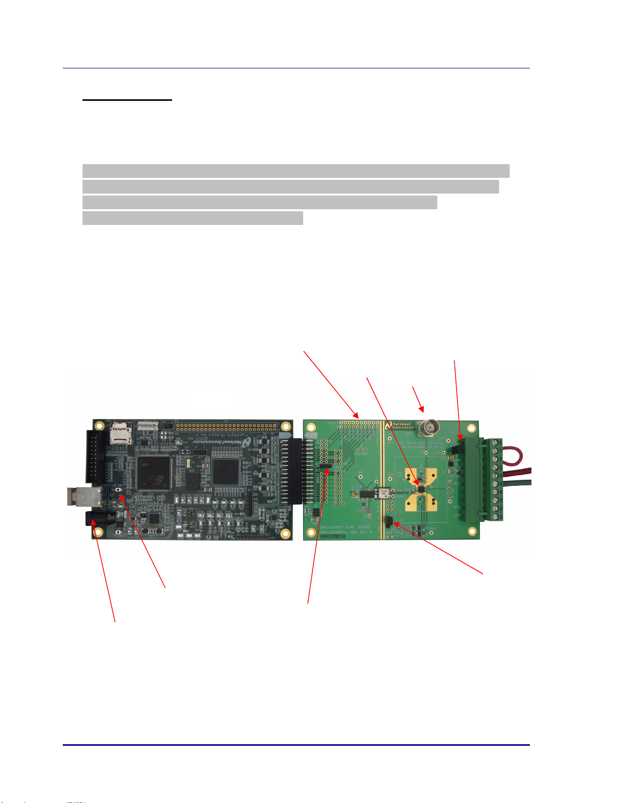
Complete evaluation system is shown elow
SPIO4
DAC161P997
CPU Reset
VDDIO
Header: SHUNT MUST ALWAYS
BE IN POSITION [1, 2] (here: LEFT and
CENTRE)
5V Supply
LOCAL LDO Header: shunt
is inserted y default
ERRLVL SEL Header: shunt is
inserted in position [1,2]
(here: COM and CENTRE)
SWIF t
est points
HART input

National Semiconductor
DAC161P997EVAL User’s Guide
2011 National Semiconductor Corporation Page 5 of 11 Rev: 0.00
4. Default Set-Up and Power-Up
As shipped the DAC161P997 Test Board is configured to e powered directly from the 0-20mA loop.
Local LDO (LM2936) provides 3.3V to DAC161P997 y stepping down the loop supply.
The loop is connected via terminals 5 and 6 of J1 connector. The optional shunt etween terminals 2
and 3 will power up the on oard diagnostic LEDs.
Jumper block Shunt position Function
LOCAL LDO in Connects the output of the 3.3V LDO to the VD (VA) rail of the
DAC161P997
ERRLVL SEL [COM, CENTER] Sets the input to the ERRLVL pin of DAC161P997
VDDIO [1,2] Provides the rail potential to the stimulus board (SPIO-4).
Once the above jumpers are in place, turn on the 5V power supply. In the configuration
shown here the loop current sourced from OUT is 3.3mA.

National Semiconductor
DAC161P997EVAL User’s Guide
2011 National Semiconductor Corporation Page 6 of 11 Rev: 0.00
5. ALP User Interface Software
Start y either navigating START-> National Semiconductor Corp -> Analog LaunchPAD v2…. ->Analog
LaunchPAD or, if installed, y clicking desktop shortcut.
The first screen is shown elow. If the system is properly assem led the SPIO4Board 1, and PuffyDAC
should e listed in the Devices menu in the left-hand side of the window.
Click on PuffyDAC in Devices Menu to continue….

National Semiconductor
DAC161P997EVAL User’s Guide
2011 National Semiconductor Corporation Page 7 of 11 Rev: 0.00
“Information” Ta
Selecting PuffyDAC in the Devices menu will activate the PuffyDAC screen. This screen contains 6 ta s.
1. Information: Shows the asic system information
2. Registers: this ta is not activated in present release of software
3. Scripting: Python interpreter window
4. DAC161P997 Data: lets user send DAC output update data (DAC update data changes output
current at OUT pin of the device)
5. DAC161P997 Config: lets user send data destined for the DAC161P997 internal configuration
registers
6. Stimulus Config: lets user modify the operation of the SPIO4 oard (stimulus oard)
The following sections will present the ta s in order that lets the first time user produce output from
the DAC161P997 quickly.
First select “Stimulus Config” ta …..

National Semiconductor
DAC161P997EVAL User’s Guide
2011 National Semiconductor Corporation Page 8 of 11 Rev: 0.00
“Stimulus Config” Ta
Check the “SWIF Continuous mode”. Then go to “DAC161P997 Data” ta ….
Details for later:
Control Descri tion of Functionality
SWIF Baud Rate
Sets the Bud rate of the SWIF link. New entry must e followed y <ENTER> key.
NOTE: Update stops the SWIF activity. Re-start SWIF with any of the SEND uttons in
other ta s
SWIF Continuous Mode
When checked SPIO4 will continue looping through the content of the SWIF data uffer
(Continuous Mode) until STOP utton is clicked
When cleared SPIO4 sends the content of the SWIF data uffer only once (One Shot
Mode )and follows it with repeated Intra-Frame sym ol until STOP is clicked
NOTE: Updating this control stops SWIF if already active. Re-start SWIF with any of the
SEND uttons in other ta s
Set Intra-Frame Symbol=D
When checked SPIO4 sets the Intra-Frame Sym ol to D (50% duty cycle). This setting
keeps the link active at all times, even though no meaningful data is eing sent.
When cleared SPIO4 sets the Intra-Frame Sym ol to LO (0% duty cycle).
NOTE: Intra-Frame Sym ol exists only in the context of the “SWIF One Shot Mode”
NOTE: Updating this control stops SWIF if already active. Re-start SWIF with any of the
SEND uttons in other ta s
Set ERRLVL=HI
Instructs SPIO4 oard to set HI the ERRLVL input to DAC161P997. In the default set-up
that functionality is not availa le. To ena le it a jumper should e installed connecting
points marked with “A” on the DAC161P997 Test Board

National Semiconductor
DAC161P997EVAL User’s Guide
2011 National Semiconductor Corporation Page 9 of 11 Rev: 0.00
“DAC161P997 Data” Ta
Click on and type in the “Loop Current (mA)” the desired current magnitude to e produced y
DAC161P997 output. Then press green SEND utton. O serve the current….
Details for later:
Control Descri tion of Functionality
ACK Check this ox to insert and ACK sym ol in the SWIF data stream
Send Sends the data representing the output current magnitude to SWIF data uffer on
SPIO4, and activates the link to DAC161P997
Send File
Click this control to select a file as the source of SWIF data. SWIF data file is a text file
containing only ‘0’, ‘1’, ‘A’ or ‘D’ characters (representing valid SWIF sym ols). It is up
to the user to format the data frames. When file is read-in the name of the file will
appear a ove “Send File” utton and the “Loop Current” entry ox will e cleared.
Sto Stops SWIF activity
Check ACK, NACK
SPIO4 monitors the num er of A sym ols issued y the SWIF. Each sym ol issued
increments the ACK count.
The num er of responses from the DAC161P997 is also eing monitored: for every A
issued y SWIF the lack of res onse from DAC161P997 increments the NACK count.
Both counters are cleared y STOP followed y SEND

National Semiconductor
DAC161P997EVAL User’s Guide
2011 National Semiconductor Corporation Page 10 of 11 Rev: 0.00
“DAC161P997 Config” Ta
Control Descri tion of Functionality
8-bit Value (bin) Enter a string of ‘0’ and ‘1’ characters representing configuration data for each of the
DAC161P977 internal registers
ACK same as in “DAC161P997 Data” ta
Send Sends the register address and data to the SWIF data uffer on SPIO4, and activates the
link to DAC161P997
STOP same as in “DAC161P997 Data” ta
Check ACK, NACK same as in “DAC161P997 Data” ta
Table of contents
Other National Semiconductor Evaluation Board manuals

Popular Evaluation Board manuals by other brands

Microchip Technology
Microchip Technology SOT23-3 user guide

Texas Instruments
Texas Instruments DIR9001 user guide

ON Semiconductor
ON Semiconductor AP0100AT2L00XUGAH-GEVB user manual

Texas Instruments
Texas Instruments LM20133 user guide

Texas Instruments
Texas Instruments PGA308 user guide

Fujitsu
Fujitsu SK-96380-120PMC user guide

Texas Instruments
Texas Instruments TPS79801DCQEVM-434 user guide

Analog Devices
Analog Devices UG-102 user guide

Texas Instruments
Texas Instruments TPD1E04U04 user guide

Analog Devices
Analog Devices ADA4432-1BCP-EBZ user guide

Texas Instruments
Texas Instruments AN-1662 LMV551 user guide

Analog Devices
Analog Devices UG-157 user guide


