Nabla Instruments MiniP7 Use and care manual

1
M
INI
P7
A
NALOG
D
RUM
C
OMPUTER
MiniP7
V2.03
Assembly and User’s Manual
©2018

2
MiniP7 Index
1.
Thank you.................................................................................................................... 1
2.
ntentionally Blank ...................................................................................................... 1
3.
Kit Content .................................................................................................................. 2
4.
Assembling the Kit (Assembly Manual) ...................................................................... 3
4.1.
Assembly of TH Components and Spacers........................................................... 3
4.1.1.
Population of the LEDs.................................................................................. 3
4.1.2.
Population of the Trimmers.......................................................................... 4
4.1.3.
Population of the Slide Pots & Potentiometer ............................................. 5
4.1.4.
Placing the Rocker Switches ......................................................................... 6
4.1.5.
Population of the Jacks ................................................................................. 6
4.1.6.
Population of the Push Buttons.................................................................... 7
4.1.7.
Population of the Header ............................................................................. 8
4.1.8.
Mounting of the Spacers............................................................................... 8
4.2.
Tuning the MiniP7 ................................................................................................ 9
4.2.1.
White Noise Level ....................................................................................... 10
4.2.2.
Frequencies................................................................................................. 10
4.3.
Mounting the Front Panel .................................................................................. 11
4.3.1.
Front Panel.................................................................................................. 11
4.3.2.
Knobs........................................................................................................... 11
4.3.3.
Connecting the Power Supply..................................................................... 11
5.
Playing the MiniP7 (User’s Manual).......................................................................... 12
5.1.
Stand Alone ........................................................................................................ 12
5.1.1.
Selecting and Deselecting Rhythms and Combinations ................................. 12
5.2.
Using External Clock and Sync............................................................................ 13
5.2.1.
ntroduction to external clocking. .................................................................. 13
5.2.2.
Functionality of the external clock and sync. ................................................. 13
6.
Specifications ............................................................................................................ 14
6.1.
Technical Spec. ................................................................................................... 14
6.2.
Dimensions......................................................................................................... 15
6.3.
Ref Des Positions................................................................................................ 16

1
1. Thank you
for choosing this rhythm computer.
It’s a unique clone for sound and feeling of the famous Minipops7
TM
as used throughout
several parts of world renown music by Jean Michelle Jarre.
The MiniP7 has been designed to mimic the ‘spirit’ of the Minipops7
TM
as good as
possible.
Please read the assembly and operating instructions carefully to ensure the unit’s fullest
performance.
2.
Intentionally Blank

2
3. Kit Content
This summary is an overview of all parts in the kit with exclusion of the SMD populated PCB, the
Front Panel and the speed knob. To be updated
Comment Designator Description Picture Quantity Manufacturer Order
Code Supplier 1 Supplier Part Number 1
Bolt_M2.5x6_
Bolt1, Bolt2, Bolt3, Bolt4, Bolt5,
Bolt6, Bolt7, Bolt8, Bolt9,
Bolt10, Bolt11, Bolt12
Bolt_M2.5x6_
12 M2.56
PRA2MCS100- Farnell 1420030
Led_Red D21 Standard LEDs - Through
Hole 3MM FLAT TOP RED 1 WP424SRDT Mouser 604-WP424SRDT
Led_Green D22 Standard LEDs - Through
Hole 3MM FLAT TOP Green 1 WP424GDT Mouser 604-WP424GDT
HDR_2x5 HDR1 HDR_2x5
1 1056437 Farnell 1056437
1502-03 J1, J7, J8 1502-03 Wired Panel Mount
3 1502 03 Farnell 1270966
MH_SPCR_M2.5x8x4.5 MH1, MH2, MH3, MH4, MH5,
MH6
MH_SPCR_M2.5x8x4.5
6 24462 Mouser 534-24462
10k_Lin_Slide_45 P2, P4, P9, P14, P15 Slide Potentiometers
15MM SHAFT NO DET
45MM STRK SNG AUD
5PTA4543-
2015DPA103 Mouser 652-
PTA45432015DPA10
100KB_PTV09_4025FB104
P6 Pot_100k_Lin_BOURNS_PTV
09A-4025F-B102 1 PTV09A-4025F-B104 Mouser 652-PTV09A4025FB104
200R P1 Trimmer Resistors -
Through Hole 1/4" SQ
V/ADJ 200
1 T73YP201KT20 Mouser 72-T70YP-200
500R P5, P11 Trimmer Resistors -
Through Hole 1/4" SQ
V/ADJ 500
2 T73YP501KT20 Mouser 72-T70YP-500
1k P3, P12, P13, P16, P18 Trimmer Resistors -
Through Hole 1/4" SQ
V/ADJ 1K
5 T73YP102KT20 Mouser 72-T70YP-1K
500k P7 Trimmer Resistors -
Through Hole 1/4" SQ
V/ADJ 500k
1 T73YP504KT20 Mouser 72-T70YB-500K
10k P8, P10 Trimmer Resistors -
Through Hole 1/4" SQ
V/ADJ 10K
2 T73YP103KT20 Mouser 72-T70YP-10K
B3W-9000-Y1N Sw1, Sw2, Sw3, Sw4, Sw5, Sw6,
Sw7, Sw8, Sw9, Sw10
Illuminated Tactile
Switches Illuminated Ylw
LED White Cap
10 B3W-9000-Y1N Farnell 1573163
DPDT Sw11, Sw12 Toggle Switches ON-OFF .45
FLAT .350 BUSHNG SOLDER
LUG 6A 2 M2021ES1W01 Mouser 633-M2021ES1W01
Push_Button Sw13 Tactile Switches OFF-(ON)
HI OPR FRCE EXT ACT SCLP
GRY CAP 1 JB15HAP-1H Mouser 633-JB15HAP-1H

3
4. Assembling the Kit (Assembly Manual)
4.1. Assembly of TH Components and Spacers
See Technical Spec for enlarged view.
4.1.1. Population of the LEDs
Mount the LEDs with the pin enlargement just above the PCB. Long Pin is Anode and should be the upper
pin. The shortest pin is Cathode and should connect to the SOT23 Transistor.
Done
Green Led
Green Led (Upper) D22
Red Led
Red Led (Lower) D21

4
4.1.2. Population of the Trimmers
Done
T73YP201KT20
200 Ohm marked 201
P1
T73YP501KT20
500 Ohm marked 501
P5, P11
T73YP102KT20
1 k Ohm marked 102
P3, P12, P13, P16, P18
T73YP103KT20
10 k Ohm marked 103
P8, P10
T73YP504KT20
500 k Ohm marked 504
P7

5
4.1.3. Population of the Slide Pots & Potentiometer
Done
652
-
PTA45432015DPA10
10k – 50k Slide Pot
P2, P4, P9,
P14, P15
100KB_PTV09_4025FB104
9mm pot meter
100k Lin (can be 50k as well)
P6

6
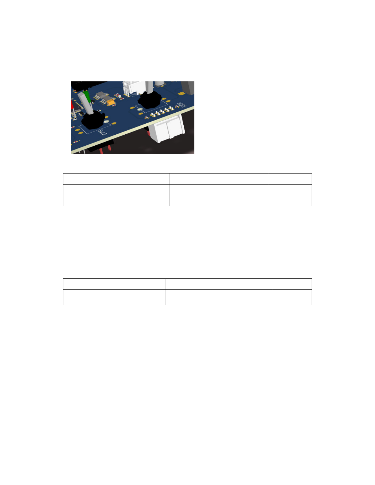
4.1.4. Placing the Rocker Switches
Sw 12 is only used as a SPDT, while Sw 11 is used as a DPDT
Done
M2021ES1W01
DPDT switch NKK
Sw 11, Sw 12
4.1.5. Population of the Jacks
Although this can be done at this time, it may
be better to assemble the jacks after the PCB
has been put on the front panel.
n the latter case be careful not to scratch the
front panel. The jacks will be at their correct
height and the pins can be bent to solder
direct to the PCB at the right vertical position.

7
Done
1502-03 Jack 3.5mm
J1, J7, J8
4.1.6. Population of the Push Buttons
Done
B3W-9000-Y1N
Sw1, Sw2, Sw3, Sw4, Sw5, Sw6, Sw7,
Sw8, Sw9, Sw10
JB15HAP
-
1H
Sw13
8
4.1.7. Population of the Header
The boxed header has to be mounted
on the bottom side of PCB.
Pin 1 should be at the lower edge of the
board.
Done
1056437 Boxed Header 2x5
HDR 1
4.1.8. Mounting of the Spacers
Mount 6 spacers at their positions using an M2.5 x 6 mm bolt. No springs are foreseen. One can
always add a spring or put some lacquer to avoid unintentional loosening of the bolt.
Done
MH_SPCR_M2.5x8x4.5 Spacer
Bolt_M2.5x6_ Bolt
MH1,MH2, MH3, MH4, MH5, MH6
Table of contents


