Mytee 304022T User manual

Page 1
Double Truss Building
Model# 304022T
L12.2 x W9.14x H6.7m
Assembly Instructions

Page 2
RECOMMENDED TOOLS
Equipment List
Speed Wrench
22#.23#.24#
Hammer (30lb)
Rope (12#)
Long Tape (50m)
Hammer Drill*1
Lifter*2
Crane*1
Forklift*1
Protective
equipment

Page 3
YOU MUST READ THIS DOCUMENT BEFORE YOU BEGIN TO ASSEMBLE THE SHELTER.
Thank you for purchasing our shelter. When properly assembled and maintained, this product will
provide years of reliable service. These instructions include helpful hints and important information
needed to safely assemble and properly maintain the shelter. Please read these instructions before you
begin.
If you have any questions during the assembly, please contact local dealer for assistance.
SAFETY PRECAUTIONS
. Wear eye protection.
. Wear head protection
. Wear gloves when handling metal tubes
. Use a portable GFCI (Ground Fault Circuit Interrupter) when working with power tools and cords.
. Do not climb on the shelter or framing during or after construction.
. Do not occupy the shelter during high winds, tornadoes, or hurricanes.
. Provide adequate ventilation if the structure is enclosed.
. Do not store hazardous materials in the shelter.
. Provide proper ingress and egress to prevent entrapment.
ANCHORING INSTRUCTIONS
Prior to assembling this shelter, please read the MUST READ document included with the shipment.
WARNING: The anchor assembly is an integral part of the shelter construction. Improper anchoring
may cause shelter instability and failure of the structure. Failing to anchor the shelter properly will void
the manufacturer’s warranty and may cause serious injury and damage.
LOCATION
Choosing the proper location is an important step before you begin to assemble the structure.
The following suggestions and precautions will help you determine whether your selected location is the
best location.
. Never erect the structure under power lines.
. Identify whether underground cables and pipes are present before preparing the site or anchoring the
structure.
. Location should be away from structures that could cause snow to drift on or around the building
. Do not position the shelter where large loads such as snow and ice, large tree branches, or other
overhead obstacles could fall.
. Your shelter’s cover can be quickly removed and stored prior to severe weather conditions. If strong
winds or severe weather is forecast in your area, we recommend removal of cover.
SITE
After choosing a location, proper preparation of the site is essential. The following site characteristics will
help ensure the integrity of the structure.
. The support structure must be level to properly and safely erect and anchor the frame.
. Drainage: Water draining off the structure and from areas surrounding the site should drain away from
the site to prevent damage to the site, the structure, and contents of the structure.
WARNING: The individuals assembling this structure are responsible for designing and furnishing all
temporary bracing, shoring and support needed during the assembly process. For safety reasons, those
who are not familiar with recognized construction methods and techniques must seek the help of a
qualified contractor.

Page 4
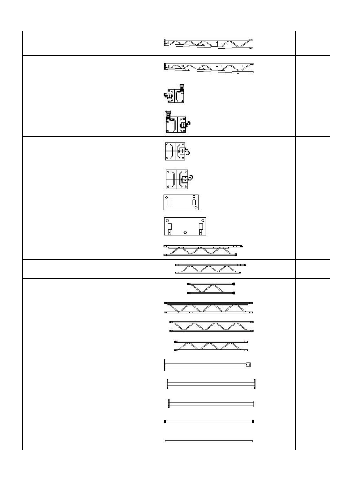
Parts List of 304022 Double Truss Buildings
No.
Parts Name
Parts Drawings
Q'ty
Box No.
1
top truss for 3rd arch
1
B
1A
top truss for 1st arch(front wall)
1
B
1B
top truss for 5th arch (back wall)
1
B
1C
top truss for 2nd and 4th arch
2
B
2
truss for 3rd arch
2
B
2A
truss for 1st and 5th arch(front&back
wall)
4
B
2B
truss for 2nd and 4th arch
4
B
3
truss for 3rd arch
2
B
3A
truss for 1st and 5th arch(front&back
wall)
4
B
3B
truss for 2nd and 4th arch
4
B
4
narrowed truss for 3rd arch
2
B
4A
narrowed truss for 1st and 5th
arch(front&back wall)
3
B
Page 5
4B
narrowed truss for 2nd and 4th arch
4
B
4C
narrowed truss for 1st arch ( front wall)
1
B
5L
corner base plate (left) for 1st and 5th
arch
2
B
5R
corner base plate (right) for 1st and 5th
arch
2
B
6L
middle base plate (left) for 2nd, 3rd, 4th
arch
3
B
6R
middle base plate (right) for 2nd, 3rd,
4th arch
3
B
7
base plate for front wall (with square
tube)
2
B
7A
base plate for back wall (with square
tube)
3
B
8
upper upright of front door
2
B
8A
upper truss post for back wall
2
B
8B
upper truss post for back wall-middle
1
B
9
lower truss post for front door
2
B
9A
lower truss post for back wall
3
A
9B
middle truss post for back wall
1
B
10
side rail for front and back wall
4
B
10A
middle rail for back wall-lower
2
B
10B
middle rail for back wall-upper
2
B
11
purlins
28
B
12
bottom tension tube for front and
back wall-side
4
B

Page 6
12A
bottom tension tube for back
wall-middle
2
B
13
self adhesive felt
30+2
A
13A
cable tie for fixing felt No.13
30+2
A
14
tension tube for roof cover
8+2
B
15
front door bracing tube
6+6
B
16
front door bracing tube-bottom
1+1
B
17
expansion bolt
50+6
A
18
hex bolt for truss arches connection
120+20
A
18A
hex bolt for base plate connection
40+6
A
19
hex bolt for purlins connection
35+6
A
20
bolt for connection plate
34+4
A
21
bolt for door post connection
80+10
A
21A
carriage bolt for rail (installing hand
winch) No.33
2+2
A
22
Φ32/Φ40mm Plastic plug
13+4
A
23
roof steel ropes
16
B
24
side steel ropes
8
B
24A
bottom steel ropes
8
B
25
M12 Buckle bolt
32
A
25A
Clip Lock
64+4
A
26
roof cover
1
A

Page 7
27
back cover
1
A
28
Φ8 nylon ropes
11+2
A
29
front cover
1
A
30
tension straps
42+2
A
31
hanger rod(Φ48*1140mm)
1
B
32
door beam(Φ60*1940/2050mm)
1+1
B
33
winch bracket(□40*60*2010mm)
1
B
34
PVC pipe
4m*8+2.3m
*2
A
35
winch
1
A
36
pole for pulling door
1
B

Page 8
INSTALLATION PROCESS
A—BASE PLATES INSTALLATION
Please refer to the below diagram to mark the position of base plates
The measurement is from center to center of base plates. Referring to the diagram and confirm the
place of base plates. ENSURE THAT THE FOUNDATION IS SQUARE.
Note: The expansion bolt (No.17) applies for fixing base plate on concrete ground.
B—FRAME INSTALLATION
First Arch and Front Wall Installation
1. Find Trusses (No.1A, 2A, 3A, 4A and 4C) for first arch and connect them by hex bolt M8x70
(No.18).

Page 9
2. Find relative parts of posts and rails for front wall and assemble them according to the below
diagram.
Second Arch and Fourth Arch Installation
3. Find Trusses (No.1C, 2B, 3B and 4B) for second and fourth arch and connect them by hex bolt
M8x70 (No.18).

Page 10
Third Arch Installation
4. Find Trusses (No.1, 2, 3 and 4) for third arch and connect them by hex bolt M8x70 (No.18).
Table of contents
Other Mytee Shelter manuals


Popular Shelter manuals by other brands


Storage Canopy
Storage Canopy C3340R Assembly instructions

Frabill
Frabill ICE HUNTER 195 instruction manual

Shelters4Less
Shelters4Less SR1588 Assembly instructions

Sealey
Sealey Power Products GSS150819SD instructions

Crivit
Crivit 104155 Operation and safety notes

No Butts Bin
No Butts Bin SR1558-F Assembly instructions