Mul-t-lock Padlocks NE Series User manual

Service Manual
Padlocks

Table of Contents
NE
Series Padlock
NE10L; NE12L; NE14L ............................................................................................................................................................... 2
NE10H; NE12H; NE14H ........................................................................................................................................................... 3
Disassembly - NE10L, NE12L, NE14L; NE10H, NE12H, NE14H .............................................................. 4
Assembly - NE10L, NE12L, NE14L; NE10H, NE12H, NE14H .................................................................... 6
NE8G ...................................................................................................................................................................................................... 8
NE10G ....................................................................................................................................................................................................9
Disassembly - NE8G; NE10G ........................................................................................................................................ 10
Assembly - NE8G; NE10G ............................................................................................................................................... 11
SBNE12 - Sliding Bolt ............................................................................................................................................................. 12
Disassembly - SBNE12 ....................................................................................................................................................... 13
Assembly - SBNE12 .............................................................................................................................................................. 15
SBNE10 - Sliding Bolt ............................................................................................................................................................. 17
Disassembly - SBNE10 ....................................................................................................................................................... 18
Assembly - SBNE12 .............................................................................................................................................................. 20
Dimensions - NEG; NEL; NEH ......................................................................................................................................... 22
Dimensions - SBNE ................................................................................................................................................................ 23
CSeries Padlock
Removable Shackles C10, C13 & C16 ........................................................................................................................ 24
Disassembly Instructions ................................................................................................................................................. 25
Assembly Instructions ....................................................................................................................................................... 27
Pop-Open Shackles C10, C13 & C16 ............................................................................................................................ 29
Disassembly Instructions ............................................................................................................................................... 30
Pop-Open Shackle C8 ............................................................................................................................................................. 32
Disassembly Instructions ............................................................................................................................................... 33
Conversion between Removable Shackle and Pop-Open Shackle ....................................................... 35
Single Pin ........................................................................................................................................................................................... 36
Disassembly Instructions ............................................................................................................................................... 37
SBC-13 Sliding Bolt .................................................................................................................................................................... 39
Disassembly Instructions ............................................................................................................................................... 40
Shackles & shells part numbers ..................................................................................................................................... 43
GSeries Padlock
G-47 ....................................................................................................................................................................................................... 44
G-47P .................................................................................................................................................................................................. 45
G-55 ..................................................................................................................................................................................................... 46
G-55P .................................................................................................................................................................................................. 47
G-60 ..................................................................................................................................................................................................... 48
Assembly Instructions ...................................................................................................................................................... 49
Security Pin Assembly Instructions .......................................................................................................................... 51
Extreme weather cover for G-47, G-55 .................................................................................................................... 52
SBG - Sliding Bolt ........................................................................................................................................................................ 54
Disassembly & Assembly Instructions ................................................................................................................. 55
Round Padlock ............................................................................................................................................................................. 56
Disassembly & Assembly Instructions ................................................................................................................. 58
HaspLock ................................................................................................................................................................................ 60
2
E Series PadlockNE Series Padlock
2
10
1
7
3
8
12
4
5
11
9
6
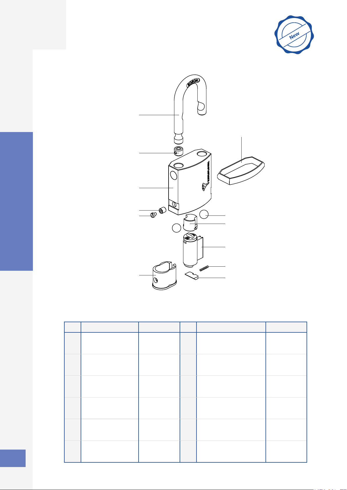
NE Series Padlock
No. Part Part number No. Part Part number
1 Padlock body 10 - 28500141
12 - 28500161
14 - 28500181
7 Slotted head screw M3X4 31810304
2 Shackle 10 - 28500142
12 - 28500162
14 - 28500182
8 Cylinder holder 28500146
3 Shackle adaptor 10 - 28500147
12 - 28500167
14 - 28500187
9 Ball St. Steel 10 - 89400021
12 - 89400021
14 - 89400024
4 Threaded plug 10 - 28500148
12 - 28500168
14 - 28500188
10 Shutter 28500144
5 Activator cam 10 - 28500143
12 - 28500163
14 - 28500183
11 Cylinder assy N.A
6 Bumper 10 - 28500134
12 - 28500164
14 - 28500164
12 Spring 28200150
NE10L; NE12L; NE14L

3
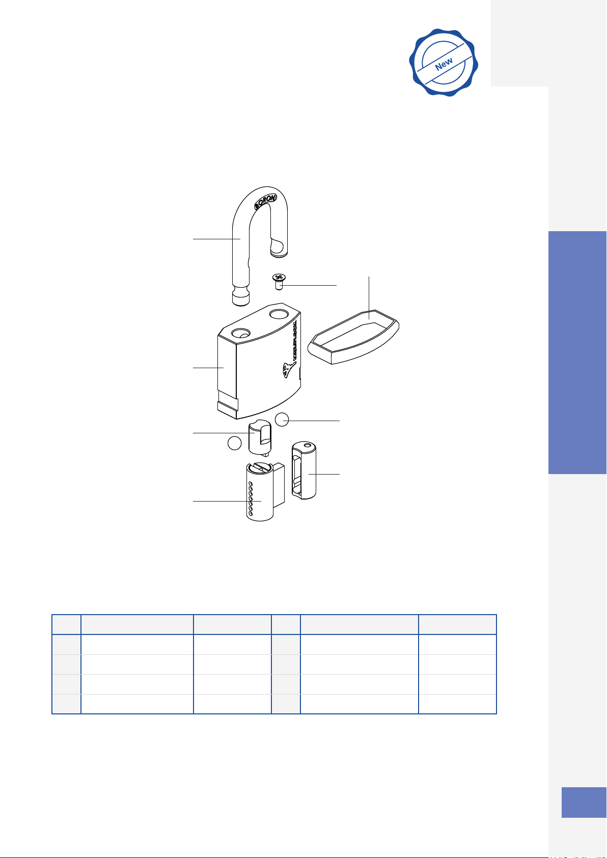
E Series PadlockNE Series Padlock
1
2
3
4
5
6
7
8
9
10
11
12
No. Part Part number No. Part Part number
1 Padlock body 10 - 28500151
12 - 28500171
14 - 28500191
7 Slotted head screw M3X4 31810304
2 Shackle 10 - 28500142
12 - 28500162
14 - 28500182
8 Cylinder holder 28500146
3 Shackle adaptor 10 - 28500147
12 - 28500167
14 - 28500187
9 Ball St. Steel 10 - 89400021
12 - 89400021
14 - 89400024
4 Threaded plug 10 - 28500148
12 - 28500168
14 - 28500188
10 Shutter 28500144
5 Activator cam 10 - 28500143
12 - 28500163
14 - 28500183
11 Cylinder assy. N.A
6 Bumper 10 - 28500134
12 - 28500164
14 - 28500164
12 Spring 28200150
NE Series Padlock
NE10H; NE12H; NE14H

4
E Series PadlockNE Series Padlock
•Removebumper(6).Useatscrewdrivertoremoveslotted head screw (7).
1
6
•Unlockthepadlockwiththeoperangkey.Pullouttheshackle(2)and
shackleadaptor(3)unlthreadedplug(4)holeisnotblocked.
2
2
Service Instructions
Disassembly - NE10L, NE12L, NE14L; NE10H, NE12H, NE14H
7
3 4
3
•Use standard M3 screw to remove the threaded plug (4).
Note:Forconvenienceremoval/inseronofthethreadedpluguselongscrew
(15-20mm). Screw only few turns and pull it out.
4
M3 Screw

5
E Series PadlockNE Series Padlock
•Take out cylinder (11) and cylinder holder (8).
•Remove activator cam (5) and the two steel balls (9).
5
4
9
•Remove cylinder (11) from cylinder holder (8).
•Remove shutter (10) and spring (12).
•Remove shackle (2) and shackle adaptor (3).
5
11
8
6
2
8
11
10
12
3

6
E Series PadlockNE Series Padlock
•Insert two steel balls (9).
•Insert activator cam (5) as described in diagram 5A.
Note:Acvatorcam(5)isnotsymmetrical.
5
2
9
•Assemble shutter (10) and spring (12) in cylinder holder (8).
•Insert cylinder (11).
•Insert shackle adaptor (3) and shackle (2) into padlock body as illustrated.
3
11
8
1
2
Service Instructions
Assembly - NE10L, NE12L, NE14L; NE10H, NE12H, NE14H
10
12
3
5A
Smaller groove toward the
longer leg of the shackle

7
E Series PadlockNE Series Padlock
•Lockthepadlockandremoveoperangkey.
•Useatscrewdrivertoscrewslotted head screw (7).
•Assemble bumper (6).
6
6
7
•Litheshackle(2)andshackleadaptor(3)unlthreadedplugholeisnotblocked.
•Push threaded plug (4) all the way in as illustrated. Remove the M3 screw.
Note:Forconvenienceremoval/inseronofthethreadedpluguselongscrew
(min. 15-20mm). Screw only few turns.
5
4
M3 Screw
4
•Insertcylinder(11)withcylinderholderintopadlock.Withoperangkeyverify
properoperaonofthepadlock.
11
8

8
E Series PadlockNE Series Padlock
2
5
1
4
3
6
7
8
No. Part Part number No. Part Part number
1 Padlock body 28500121 5 Phillips head screw M4X8 31330408
2 Shackle 28500122 6 Ball St. Steel 89400020
3 Activator cam 28500123 7 Cylinder holder 28500113
4 Cylinder assy. N.A.
Padlock
9
E Series PadlockNE Series Padlock
2
5
1
4
3
6
7
8
No. Part Part number No. Part Part number
1 Padlock body 28500131 5 Phillips head screw M4X8 31330408
2 Shackle 28500132 6 Ball St. Steel 89400020
3 Activator cam 28500133 7 Cylinder holder 28500113
4 Cylinder assy. N.A.
Padlock
This manual suits for next models
3
Table of contents
Other Mul-t-lock Lock manuals


