MTU 12 V 4000 C20 User manual

Operating Instructions
Diesel engine
12 V 4000 C10, C10R, C11, C11R
12 V 4000 C20, C20R, C21, C21R
16 V 4000 C10, C11, C11R
16 V 4000 C20, C20R, C21, C21L
MS150049/02E

Printed in Germany
© 2012 Copyright MTU Friedrichshafen GmbH
This Publication is protected by copyright and may not be used in any way whether in whole or in part without the prior
written permission of MTU Friedrichshafen GmbH. This restriction also applies to copyright, distribution, translation, micro‐
filming and storage or processing on electronic systems including data bases and online services.
This handbook is provided for use by maintenance and operating personnel in order to avoid malfunctions or damage
during operation.
Subject to alterations and amendments.

Table of Contents
1 Safety
1.1 Important provisions for all MTU engines or
systems 5
1.2 Personnel and organizational requirements 6
1.3 Transport 7
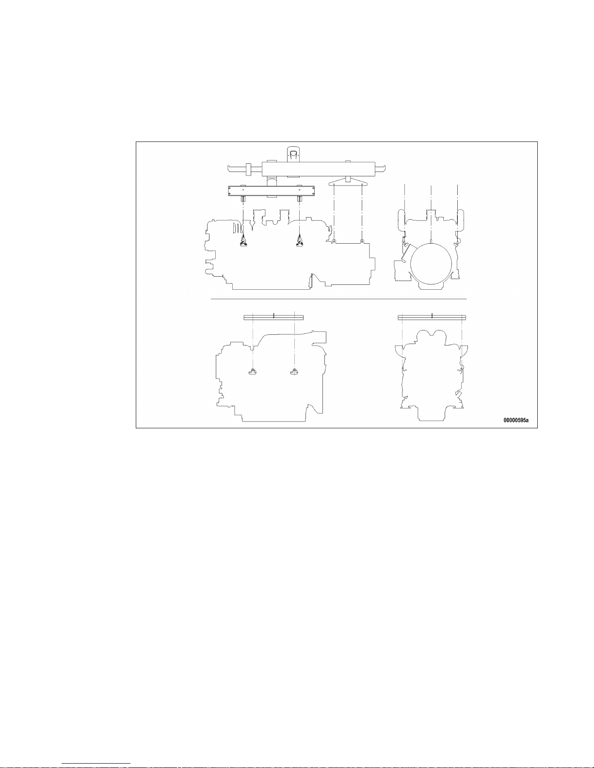
1.4 Crankshaft transport locking device 8
1.5 Crankshaft transport locking device – For
transport with flanged-on generator 11
1.6 Safety regulations for startup and operation 13
1.7 Safety regulations for maintenance and
repair work 14
1.8 Fire prevention and environmental
protection, auxiliary materials, fluids and
lubricants 17
1.9 Standards for safety messages in the text 19
2 General Information
2.1 Engine side and cylinder designations 20
2.2 Engine – Overview 21
2.3 Sensors, actuators and injectors –
Overview 23
3 Technical Data
3.1 Engine data 12 V 4000 C10, C10R, C11,
C11R 26
3.2 Engine data 16 V 4000 C10, C11, C11R 29
3.3 Engine data 12 V 4000 C20, C20R, C21,
C21R 32
3.4 Engine data 16 V 4000 C20, C20R, C21,
C21L 35
3.5 Firing order 38
3.6 Engine – Main dimensions 39
4 Operation
4.1 Putting the engine into operation after
extended out-of-service periods (>3
months) 40
4.2 Putting the engine into operation after
scheduled out-of-service-period 41
4.3 Starting the engine in manual mode 42
4.4 Operational checks 43
4.5 Stopping the engine in manual mode 44
4.6 After stopping the engine 45
4.7 Plant cleaning 46
5 Maintenance
5.1 Maintenance task reference table [QL1] 47
6 Troubleshooting
6.1 Troubleshooting 49
6.2 Fault messages from DDEC engine
governor 52
7 Task Description
7.1 Engine 72
7.1.1 Engine – Barring manually 72
7.1.2 Engine – Barring with starting system 73
7.2 Cylinder Liner 74
7.2.1 Cylinder liner – Endoscopic examination 74
7.2.2 Instructions and comments on endoscopic
and visual examination of cylinder liners 76
7.3 Crankcase Breather 78
7.3.1 Crankcase breather – Filter element
replacement 78
7.3.2 Crankcase breather (open-circuit crankcase
ventilation) – Filter element cleaning 80
7.4 Running Gear 81
7.4.1 Grounding device – Check carbon brush 81
7.4.2 Grounding device – Carbon brush
replacement 83
7.5 Valve Drive 84
7.5.1 Valve gear – Lubrication 84
7.5.2 Valve clearance – Check and adjustment 85
7.5.3 Cylinder head cover – Removal and
installation 89
7.6 Injection Pump / HP Pump 90
7.6.1 HP pump – Relief bore check 90
7.7 Injection Valve / Injector 91
7.7.1 Injector – Replacement 91
7.7.2 Injector – Removal and installation 92
7.8 Fuel System 97
7.8.1 Fuel system – Venting 97
7.9 Fuel Filter 98
7.9.1 Fuel filter – Replacement 98
MS150049/02E 2012-11 | Table of Contents | 3
DCL-ID: 0000017488 - 004

7.10 Charge-Air Cooling 99
7.10.1 Charge-air cooler – Check water drain for
coolant leakage and absence of restrictions 99
7.11 Starting Equipment 100
7.11.1 Starter – Condition check 100
7.11.2 Cold start system with ether injection – Check 101
7.12 Air Intake 102
7.12.1 Service indicator – Check 102
7.13 Lube Oil System, Lube Oil Circuit 103
7.13.1 Engine oil – Level check 103
7.13.2 Engine oil – Change 104
7.13.3 Engine oil – Sample extraction and analysis 106
7.14 Oil Filtration / Cooling 107
7.14.1 Engine oil filter – Replacement 107
7.14.2 Oil indicator filter – Check 108
7.14.3 Centrifugal oil filter – Cleaning and filter
sleeve replacement 110
7.15 Coolant Circuit, General, High-
Temperature Circuit 112
7.15.1 Engine coolant – Level check 112
7.15.2 Engine coolant – Change 113
7.15.3 Engine coolant – Draining 114
7.15.4 Engine coolant – Filling 115
7.15.5 Engine coolant pump – Relief bore check 117
7.15.6 Coolant filter – Replacement 118
7.15.7 Engine coolant – Sample extraction and
analysis 119
7.16 Low-Temperature Circuit 120
7.16.1 Charge-air coolant – Level check 120
7.16.2 Charge-air coolant – Change 121
7.16.3 Charge-air coolant – Drainage 122
7.16.4 Charge-air coolant – Filling 123
7.16.5 Charge-air coolant pump – Relief bore check 126
7.17 Engine Mounting / Support 127
7.17.1 Engine mounting – Check 127
7.18 Belt Drive 128
7.18.1 Drive belt – Condition check 128
7.19 Battery-Charging Generator 129
7.19.1 Battery-charging generator – Condition check 129
7.19.2 Battery-charging generator – Check 130
7.19.3 Battery-charging generator – Removal and
installation 131
7.19.4 Battery-charging generator – Drive belt and
belt tensioner replacement 133
7.19.5 Battery-charging generator – Drive belt
tension adjustment 135
7.20 Fan Drive 136
7.20.1 Fan drive – Adjust and check drive belt
tension 136
7.20.2 Fan drive – Drive belt replacement 138
7.21 Auxiliary PTO 139
7.21.1 Compressor – Check 139
7.22 Wiring (General) for Engine/Gearbox/Unit 140
7.22.1 Engine wiring – Check 140
7.23 Accessories for (Electronic) Engine
Governor / Control System 141
7.23.1 DDEC and connectors – Cleaning 141
7.23.2 DDEC – Checking plug-in connections 143
8 Appendix A
8.1 Abbreviations 144
8.2 MTU contact persons/service partners 147
9 Appendix B
9.1 Special Tools 148
9.2 Index 154
4 | Table of Contents | MS150049/02E 2012-11
DCL-ID: 0000017488 - 004

1 Safety
1.1 Important provisions for all MTU engines or systems
Nameplate
Engine identification is provided by the engine serial number on the nameplate.
The nameplate is located on the engine.
General information
This engine or plant may present a risk of injury or damage in the following cases:
• Incorrect use
• Operation, maintenance and repair by unqualified personnel
• Modifications or conversions
• Noncompliance with the safety instructions
Correct use
The engine or plant is intended solely for use in accordance with contractual agreements and the pur‐
pose envisaged for it on delivery.
This means that the equipment must be operated:
• Within the permissible operating parameters in accordance with the (→ engine data)
• With fluids and lubricants approved by MTU in accordance with the (→ MTU Fluids and Lubricants
Specifications)
• With spare parts approved by MTU in accordance with the associated (→ Spare Parts Catalog)
• In the original as-delivered configuration or in a configuration approved by MTU in writing (engine and
engine control/parameters)
• In compliance with all safety instructions and in adherence to all warning notices in these Operating
Instructions
• In compliance with the maintenance and repair instructions contained in these Operating Instructions,
in particular with regard to the specified tightening torques
• Appointing only qualified personnel to carry out work related to initial startup, operation, maintenance
and repair
• Contracting only workshops authorized by MTU to carry out repair and overhaul
Any other use is considered improper use and increases the risk of personnel injury or material damage
in engine/plant operation.MTU will accept no liability for such damage.
Modifications or conversions
Unauthorized modifications to the engine or plant represent a safety risk.
MTU will accept no liability or warranty claims for any damage caused by unauthorized modifications or
conversions.
Spare parts
Only genuine MTU spare parts must be used to replace components or assemblies.
MTU will accept no liability or warranty claims for any damage caused by the use of other spare parts.
MS150049/02E 2012-11 | Safety | 5
TIM-ID: 0000000860 - 018

1.2 Personnel and organizational requirements
Organizational measures of the operator
This publication must be issued to all personnel involved in operation, maintenance, repair or transporta‐
tion.
Keep it at hand at the operating site of the engine so that it is available to operating, maintenance, repair
and transport personnel at all times.
Use the manual as a basis for instructing personnel on engine operation and repair with an emphasis on
explaining safety-relevant instructions.
This is particularly important in the case of personnel who only occasionally perform work on or around
the engine or plant. This personnel must be instructed repeatedly.
For the identification and layout of the spare parts during maintenance or repair work, take photos or use
the spare parts catalog.
Personnel requirements
All work on the engine or plant shall be carried out by trained and qualified personnel only:
• Training at the MTU Training Center
• Qualified personnel specialized in mechanical and plant engineering
The operator must define the responsibilities of the personnel involved in operation, maintenance, repair
and transport.
Working clothes and protective equipment
Wear proper protective clothing for all work.
6 | Safety | MS150049/02E 2012-11
TIM-ID: 0000000874 - 020

1.3 Transport
Transport
Always use the lifting eyes on the engine and generator/gearbox when transporting gensets.
Always use the lifting eyes on the engine when transporting an engine separately.
Only use transport and lifting devices approved by MTU.
The engine/genset must only be transported in installation position: maximum permissible diagonal pull
10°.
Remove any loose parts on the genset.
Raise the engine/genset slowly. The lifting ropes or chains must not make contact with the engine or its
components. Readjust lifting device as necessary.
Pay attention to the center of gravity of the engine/genset.
For special packaging with aluminium foil: Suspend the engine/genset by the lifting eyes on the bearing
pedestal or transport by means of handling equipment (forklift truck) capable of bearing the load.
Fit the crankshaft transportation lock on the engine and fit the engine mount locking devices prior to
transport.
Secure the engine/genset such as to preclude tipping during transport. Secure such as to preclude slip‐
ping and tipping when driving up or down inclines and ramps.
Placement after transport
Place the engine/genset on a firm, flat surface only.
Make sure that the consistency and load-bearing capacity of the ground or support surface is adequate.
Never set an engine down on the oil pan unless expressively authorized to do so by MTU on a case-to-
case basis.
MS150049/02E 2012-11 | Safety | 7
TIM-ID: 0000002618 - 006

1.4 Crankshaft transport locking device
Special tools, Material, Spare parts
Designation / Use Part No. Qty.
Torque wrench, 10-60Nm F30452769 1
Torque wrench, 60-320Nm F30452768 1
Engine oil
Note: The transport locking device on both sides protects the crankshaft bearings from shocks and possible
vibration damage during engine transport.
For installation and removal of the transport locking device, follow the instructions
below:
1. The transport locking device on both sides must remain installed as long as possible during engine in‐
stallation in order to avoid damage.
2. Prior to every engine transport (without generator) , the transport locking device on both sides must be
installed according to the instructions.
3. If the engine is to be moved together with the generator, the transport locking device for the generator
must also be installed (→ Page 11).
4. Always use the screws supplied with or installed in the transport locking device to secure it on the en‐
gine.
5. Starting or barring the engine is allowed only with the transport locking device removed. If the generator
is already mounted on the engine, ensure that the transport locking device of the generator is also re‐
moved.
6. Attach this documentation to a highly visible area of the engine.
Removing the transport locking
device from driving end (KS),
version A
1. Remove parts (1) to (8) from engine.
Spacer sleeves (5), optional.
2. Store the removed parts of the transport
locking device carefully for possible reuse.
8 | Safety | MS150049/02E 2012-11
TIM-ID: 0000040575 - 001

Installing the transport locking
device on driving end (KS), version
A
1. Screw holder (4) with spacer sleeves (5)
and screws (6) onto crankshaft. Spacer
sleeves (5), optional.
2. Tighten screws (6) with torque wrench to specified tightening torque.
Name Size Type Lubricant Value/Standard
Screw M16 Tightening torque (Engine oil) 160Nm +16Nm
3. Screw nut (3) with washer (2) onto holder (4). Screw on carrier (1) with washer (7) and nut (8) and tight‐
en nut (8) to the specified tightening torque using the torque wrench.
Name Size Type Lubricant Value/Standard
Nut M24 Tightening torque (Engine oil) 100Nm +10Nm
4. Secure with nut (3).
5. Mark the engine as "Fitted with transport locking device".
Removing the transport locking
device from driving end (KS),
version B
1. Release the locknuts (2) on both sides of
the flywheel housing, remove screw (3) and
take off holder (8).
2. Unscrew screws (5) and remove with wash‐
ers (4), cover plate (7) sign (6) and
plates (1).
3. Store the removed parts of the transport
locking device carefully for possible reuse
together with this documentation.
MS150049/02E 2012-11 | Safety | 9
TIM-ID: 0000040575 - 001

Installing the transport locking
device on driving end (KS), version
B
1. Secure plate (1) with screws (5) and washers (4) together with cover plate (7) at the bores on both sides
of the flywheel housing and tighten to the specified tightening torque.
Name Size Type Lubricant Value/Standard
Screw M16 Tightening torque (Engine oil) 250Nm +25Nm
2. Screw locknut (2) onto screws (3) up to the end of the thread.
3. Insert holder (8) through opening in plate (1) and secure with screw (3).
4. Tighten screws (3) alternately with torque wrench to the specified tightening torque.
Name Size Type Lubricant Value/Standard
Screw M10 Tightening torque (Engine oil) 30Nm +3Nm
5. Place locknuts (2) of screw (3) in position on both sides of plate (1) and lock.
6. Fit sign (6) to mark the engine as "Fitted with transport locking device".
10 | Safety | MS150049/02E 2012-11
TIM-ID: 0000040575 - 001
This manual suits for next models
11
Table of contents
Other MTU Engine manuals

MTU
MTU 12 V 1600 R50 User manual

MTU
MTU 12V2000Gx6x User manual

MTU
MTU 8V2000Mx4x User manual

MTU
MTU 12V4000C*5 series User manual

MTU
MTU 12 V 4000 M63 User manual

MTU
MTU 12 V 2000 Gx6F User manual

MTU
MTU 8V 4000 Lx2 x User manual

MTU
MTU 8V2000M40A User manual

MTU
MTU Detroit Diesel 183 Series User manual

MTU
MTU 12 V 4000 Lx4 User manual

MTU
MTU 12V4000L62FB User manual

MTU
MTU 16V4000R43 User manual

MTU
MTU 20V4000L63 User manual

MTU
MTU 20V4000G44F User manual

MTU
MTU 12V2000M94 User manual

MTU
MTU 12 V 4000 L62FB User manual

MTU
MTU 16V4000M*3 series User manual

MTU
MTU 8V4000L63 User manual

MTU
MTU 20 V 4000 G83 User manual

MTU
MTU 8V4000L33F User manual


