
MrCool UNIVERSAL MDUCC150 Series Quick start guide

Please read this manual carefully before installation and keep it for future reference.
Owner & Installation
Manual
UNIVERSAL
®
A-Coils
Model: MDUCC150**
Copyright © 2021 MRCOOL, LLC
Thank you for choosing MRCOOL. Please read this manual carefully before installation and keep it for future reference.
Due to updates and constantly improving performance, the information and instructions within this
manual are subject to change without notice. Please visit www.mrcool.com/documentation to
ensure you have the latest version of this manual.
Version Date: 4-27-21
Lorem ipsumLorem ipsum

mrcool.com
After-Sales Service .................... 14
6
Blower Speed Selection .............. 12
4
Maintenance and Care ............... 13
5
Unit Installation ........................... 6
3.1 Pre-Installation Instructions ........................... 6
3.4 Refrigerant Piping Connection ........................ 8
3.5 Condensate Removal ....................................... 9
3.2 Location ............................................................... 6
3.7 Unit Installation ..................................................11
3.9 Leak Testing, Evacuating and Charging .........11
3.6 Ductwork .............................................................11
3
3.8 Sealing Ducts .......................................................11
Optional Quick-Connect Line set Installation ...... 10
3.3 A-Coil Orientation/Position Options ............. 7
2.1 Product Description ......................................... 4
2.2 Main Components ............................................ 4
2
Product Information .................... 3
2.3 Physical Dimensions
........................................ 5
2.4 Cooling Capacity Range................................... 5
Safety Precautions ....................... 2
1
5.1 Condensate Pipe ............................................ 13
5.2 Checklist Before Seasonal Use ................... 13
5.3 Maintenance after Seasonal Use ............... 13
5.4 Parts Replacement ......................................... 13
Table Of Contents
Page 1

MRCOOL®Electric Heat Kit
Page 2mrcool.com
Safety Precautions
WARNING
Please read the manual in its entirety and be aware of all warnings and cautions before
installing, operating, or repairing.
DO NOT install this unit in a corrosive, inflammable, or explosive environment.
DO NOT install in any environment with special requirements, such as a kitchen. These factors will affect
the normal operation or shorten the service life of the unit and could cause a fire hazard or lead to serious
injury. If a unit needs to be installed in an environment with special requirements, please find a unit made
specifically for this purpose that has anti-corrosive and anti-explosion functions.
Installation must be performed by an authorized technician. Improper installation, adjustment, alteration,
service, maintenance, or use could cause fire, explosion, electrical shock, property damage, personal injury,
or death. The services of a professional installer are NOT required when the MRCOOL Quick Connect®
Pre-Charged Line Set is used in the installation.
Follow all safety codes.
Wear safety glasses, protective clothing, and work gloves.
Use a quenching cloth for brazing operations.
Have a fire extinguisher available.
In North America, installation must be performed in accordance with the requirements of the NEC and CEC
(by authorized personnel only). Consult local building codes and NEC for special requirements.
The qualified installer or agency must use factory-authorized kits or accessories when installing or
modifying this product. Refer to the individual instructions packaged with the kits or accessories when
installing. Using non-standard parts can cause water leakage, electrical shock, or fire and may cause the
unit to fail.
ELECTRICAL SHOCK HAZARD: Failure to follow this warning could result in personal injury or
death. Before installing, modifying, or servicing system, the main electrical disconnect switch
must be in the OFF position. There may be more than one disconnect switch. Lock out and tag
switch with a suitable warning label.
Read Before Installation
Incorrect installation may cause serious damage or injury.
The seriousness of potential damage or injuries is classified as either a WARNING or CAUTION.
WARNING
CAUTION
This symbol indicates ignoring instructions may cause death or serious injury.
This symbol indicates that ignoring instructions may cause moderate injury
to your person, damage to your unit, or other property.
This symbol indicates that you should NEVER perform the indicated action.
1.
2.
3.
4.
5.
6.
7.
8.
1
Safety Precautions
As with any mechanical equipment, contact with sharp sheet metal edges can result in personal injury.
Be careful while handling this equipment and wear gloves and protective clothing.

2
Product Introduction
Page 3 mrcool.com
To Our Customers;
Thank you for choosing a MRCOOL HVAC product. Please read this manual carefully before installation and
operation of the Universal™ Series A-Coil to ensure correct use and handling. In addition to the safety
precautions in the previous section, please adhere to the following guidelines and note our exceptions to
liability.
1. This appliance can be used by children aged 8 years and older and persons with reduced physical, sensory
or mental capabilities or lack of experience and knowledge if they have been given supervision or instruction
concerning use of the appliance in a safe way and understand the hazards involved. Children should not play
with the appliance. Cleaning and user maintenance should not be made by children without supervision.
2. To ensure product reliability, the unit may consume power under stand-by status to maintain normal
communication, and for preheating refrigerant and lubricant. If the unit will not be used for an extended
period, disconnect the power supply. Reconnect the power supply and preheat the unit prior to use.
3. Ensure you have selected the proper model for the operating environment. Improper selection may impact
operating performance.
4. This product has undergone strict inspection and operational testing before leaving the factory. To avoid
damage due to improper disassembly and inspection, which may impact the normal operation, please do not
disassemble the unit by yourself. Please contact MRCOOL.
5. For technical assistance, please contact MRCOOL technical support at (270) 366-0457.
6. If the product is malfunctioning and/or is inoperable, please contact MRCOOL technical support at the
aforementioned number, as soon as possible and provide the following information:
a. Product Nameplate Contents (model number, cooling/heating capacity, product serial number, factory
date)
b. Nature of Malfunction (specify the circumstances before and after the error occurred)
7. All illustrations and information in the instruction manual are for reference only. In order to improve the
product, we will continuously assess and innovate. We retain the right to make necessary revisions to the
product from time to time. We reserve the right to revise the contents of this manual without notice.
8. If the supply cord is damaged, it must be replaced by MRCOOL, a professional service agent or similarly
qualified person in order to avoid damage to the product.
9. MRCOOL, LLC assumes no responsibility for personal injury, property loss or equipment damage caused by
improper installation and commissioning, unnecessary maintenance, or failure to follow relevant federal and
state regulations, industrial standards, and the requirements of this instuction manual.
10. MRCOOL, LLC will bear no responsibilities for personal injury or property damage caused by the following:
a. Improper use of the appliance.
b. Altering, maintaining, or operating the product with non-approved equipment.
c. Altering, maintaining, or operating the product outside of the guidelines of this manual.
d. Defects caused by corrosive gas.
e. Defects caused by shipping damage.
f. Failure to abide by this instruction manual or government regulations.
g. Products made by other manufacturers.
h. Natural disasters, improper installation environment, or force majeure.

Product Information
Page 4mrcool.com
The Universal Series®A-Coil offers the perfect combination of superior product quality, operating efficiency,
operating sound levels, and value for money. The evaporator unit uses the environmentally friendly refrigerant
R410A, which is chlorine-free to help prevent damage to the ozone layer.
2.2 Main Components
2.1 Product Description
OPTIONAL
No-Vac
®
Quick Connect
®
Lineset
Gas / Liquid
Pipe Assembly
Horizontal Drain Pan
Evaporator Assembly
Vertical Drain Pan

Product Information
Page 5 mrcool.com
2.3 Physical Dimensions
Units: inch(millimeter)
Model Dimension
W D H A B
MDUCC15024/
MDUCC15036 17-1/2 (445) 21-1/4 (540) 23 (584) 15-7/8 (403) 19-3/8 (492)
MDUCC15048/
MDUCC15060 24-1/2 (622) 21-1/4 (540) 28-1/2 (724) 22-7/8 (581) 19-3/8 (492)
2.4 Cooling Capacity Range
Cooling capacity range as shown below:
Model Cooling capacity(ton)
MDUCC15024 2.0
MDUCC15048 4.0
MDUCC15036
MDUCC15060
3.0
5.0

mrcool.com
3
Unit Installation
Page 6mrcool.com
3.1 Pre-Installation Instructions
3.1.1 Checking Product Received
After receiving the product, please check it for damage that may have been caused during shipping.
Shipping damage is the responsibility of the carrier. Verify the model number, specifications, and
accessories are correct prior to installation. The distributor or manufacturer will not accept claims
from dealers for shipping damage or installation of incorrectly shipped units.
3.1.2 Before Installation
Carefully read all instructions for the installation prior to beginning the installation. Make sure you
understand each step or procedure and any special considerations are taken into account before
starting the installation. Some tools or items for the installation may need to be purchased locally.
Make sure that everything that is needed to complete the installation is on hand before you begin.
3.1.3 Codes & Regulations
This product is designed and manufactured to comply with national codes. It is the responsibility of
the installer to ensure that the product is installed in accordance with such codes and/or any
prevailing local codes/regulations. The manufacturer assumes no responsibility for any equipment
installed in violation of any codes or regulations.
NOTE: The instructions contained within this manual are intended as a general guide and do not
supersede local or national code in any way. Authorities who have jurisdiction should be
consulted before installation.
3.1.4 Replacement Parts
When reporting damages, shortages, or ordering replacement/repair parts, be sure to give the
complete product model and serial numbers that are stamped on the product. Replacement parts for
this product are available through your contractor or local distributor.
3.2 Location
WARNING
This coil is designed for indoor installation only. DO NOT install it outdoors.
The coil drain pan has a maximum service temperature of 500°F (260°C). Close spacing
may damage the drain pan and cause a leak. Please refer to the Product Specifications
for the proper use of these coils with specific furnaces, air handlers, condensers, and
line sets.
WARNING
The evaporator of the indoor unit is charged with refrigerant from the factory to
maintain pressure. The cut-off valve can only be opened when the installation process
and vacuuming procedure of the system have been completed.
.
.
Unit Installation
Page 7 mrcool.com
When installing the coil take into consideration the length of the refrigerant piping and try to minimize the
distance as much as possible. DO NOT install the air handler in a location that is either above or
below the condenser. Allow a minimum of 24 in (610 mm) in front of the unit to provide clearance for
service. When installing in an area directly over a finished ceiling (such as in an attic), an emergency drain pan
is required to be installed directly under the unit. Please refer to local and state codes for requirements.
When this unit is installed in area that may become wet, elevate the unit with a sturdy, non-porous material. In
installations that are in locations that may lead to physical damage (ex: garage), it is advised to install a
protective barrier to prevent such damage.
3.2 Location (cont.)
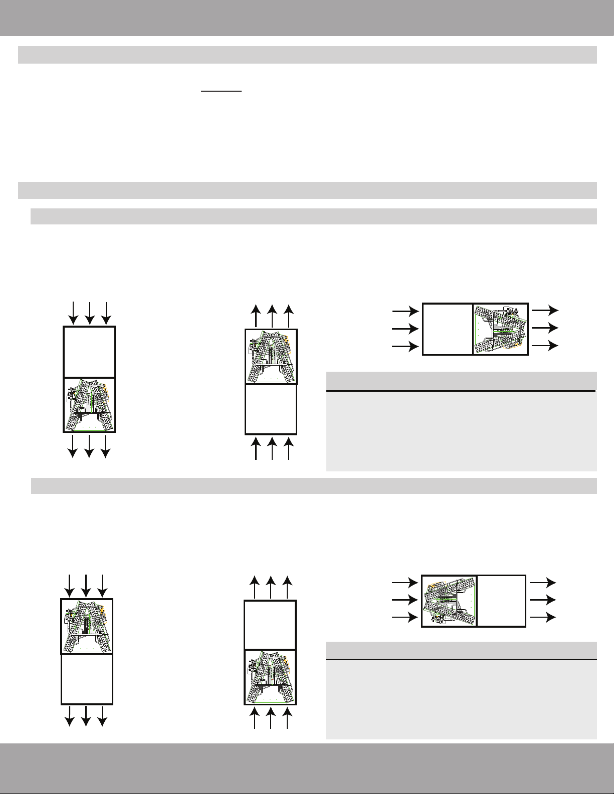
3.3 A-Coil Orientation/Position Options
3.3.1 Installing A-Coils with a furnace
Downflow Application
Furnace
A-Coil
Return Airflow
Supply Airflow to Ductwork
Upflow Application
Furnace
A-Coil
Return Airflow
Supply Airflow to Ductwork
Horizontal Right Application
Return Airflow Supply Airflow to Ductwork
3.3.2 Installing A-Coils with a modular blower
Downflow Application
Return Airflow
Supply Airflow to Ductwork
A-Coil
Modular
Blower
Return Airflow
Supply Airflow to Ductwork
Upflow Application
Return Airflow Supply Airflow to Ductwork
Horizontal Right Application
When installing the Universal A-Coils in an application with a furnace, it must be installed in a position where the
return air flows through the furnace first and then the A-Coils. From the A-Coils, the airflow is then supplied to
the ductwork to be dispersed throughout the rooms.
When installing the Universal A-Coils in an application with a modular blower, it must be installed in a position
where the return air flows through the A-Coils first and then the modular blower. From the modular blower, the
airflow is then supplied to the ductwork to be dispersed throughout the rooms.
Modular
Blower
A-Coil
Depending on your application (specifically the
size of the components in your system, cabinet
opening size and A-Coil opening size, etc.) a
transition may need to be constructed so the
furnace and A-Coil can be connected together
with a smooth transition between openings.
IMPORTANT:
Depending on your application (specifically the
size of the components in the system, modular
blower opening size and A-Coil opening size, etc.)
a transition may need to be constructed so the
modular blower and A-Coil can be connected
with a smooth transition between openings.
IMPORTANT:
A-CoilFurnace
A-Coil Modular Blower

Unit Installation
Page 8mrcool.com
3.4.1 Specifications of Connection Pipe
3.4 Refrigerant Piping Connection
Model External diameter (inch)
Gas pipe Liquid pipe
MDUCC15024/MDUCC15036 3/4 in 3/8 in
MDUCC15048/MDUCC15060
3.4.2 Piping Preperation
NOTE: If you are installing your A-Coil with the optional MRCOOL Quick-Connect®Line Set, please
skip forward to the insallation instructions for the line set on pg. 8. Once the line set installation is
complete, return to step 3.5 Condensate Removal and continue installation from there.
Solder Connection
If connecting piping with solder, make sure that any cuts made to the piping are round, burr free
(use a reamer), cleaned, and at a perfect 90° angle. Make sure the line set size matches the service
valve connector. DO NOT crimp the service valve connector if the piping is of a smaller diameter.
Failure to follow these guidelines could result in refrigerant leaking from the piping. Refer to the
illustrations below.
Oblique Rough Warped
90°
Pipe
Reamer
Point down

Unit Installation
Page 9 mrcool.com
The drain pan has a primary and secondary drain connection. Condensate removal is performed by
attaching a 3/4 in (19 mm) pipe to the evaporator coil drain pan and is terminated in accordance with
local or state plumbing/HVAC codes. The installation must include a “P” style trap that is located close to
the evaporator coil. DO NOT overtighten the drain connection as this could damage or distort the
drain pan and cause condensate leakage. Please refer to the guidelines and illustration below to best
determine how and where to run the condensate drain pipe
DO NOT connect the condensate drain pipe into a waste pipe or other pipelines which are
likely to produce corrosive fumes or an odor. Connecting to these pipes could cause the
fumes or odor to enter indoors and/or corrupt the unit.
DO NOT connect the condensate drain pipe into a rain pipe, as this could cause rain water
to enter the unit and cause property damage and/or personal injury.
The condensate drain pipe should be connected into a drain system specifically for the unit.
Screw Connection
C
onnect the pipe to the unit. Follow all instructions below. Use both a spanner and torque wrench. When
connecting the tapered screw nut, first apply Polyolester oil (POE oil) on its inner and outer surface. Then,
screw the first 3 or 4 threads by hand. Next, tighten the nut with the spanner and torque wrench. Confirm
the tightening torque by referring to the following table. DO NOT overtighten the nut as it could damage
it and cause the connection to leak.
Keep pipe connection exposed to perform the leak test.
Pipe diameter (inch) Tightening torque: ft-lbs (N·m)
1/4 in 11-22 ft-lbs (15-30 N·m)
3/8 in 26-30 ft-lbs (35-40 N·m)
1/2 in 33-37 ft-lbs (45-50 N·m)
5/8 in 44-48 ft-lbs (60-65 N·m)
3/4 in 52-55 ft-lbs (70-75 N·m)
7/8 in 59-63 ft-lbs (80-85 N·m)
3.5 Condensate Removal
.
This manual suits for next models
5
Table of contents
Other MrCool Fan manuals


Popular Fan manuals by other brands

ELTA FANS
ELTA FANS H03VV-F installation guide

Hunter
Hunter 20714 Owner's guide and installation manual

Emerson
Emerson CARRERA VERANDA CF542ORB00 owner's manual

Hunter
Hunter Caraway Owner's guide and installation manual

Panasonic
Panasonic FV-15NLFS1 Service manual

Kompernass
Kompernass KH 1150 operating instructions




