
Motoplat VC-014DS User manual

USER
MANUAL
www.motoplat.nl
VC-014DS
The Motoplat VC-014DS parts tester combines two devices:
a stator winding tester and a rectifier tester.
Once the stator is connected, the VC-014DS only take a few
seconds to identify the phase connections and then checks
the windings for any short circuits or connection failures.
The rectifier test includes checking the circuit connections
and measuring their operability.
All the above mentioned data and results will appear on a
LCD touch screen.
This small and light weighted tester was developed
according to the requirements of service stations and works
without any additional testing or measuring devises.
Stator and Rectifier Tester
ENGLISH
VERSION 2017

IMPORTANT INFORMATION
Safety Warning
Electrical devices should be installed and operated in such a way that all applicable safety requirements
are met. It is your responsibility as an installer to ensure that you idenfy the relevant safety standards and
comply with them. Failure to do so may result in damage to equipment and personal injury. In parcular,
you should study the contents of this guide carefully before installing or operang the equipment.
People who start using this product should review carefully this instrucon manual, or have had a training
from a qualied person.
The use of electrical equipment is enrely at your own risk and Motoplat® is under no circumstances
responsible for any incidental, consequenal or special damages of any kind whatsoever, including but not
limited to lost prots arising from or in any way connected with the use of the automated test equipment
or this manual.
The tester should be connected to a properly grounded outlet.
If the power cable is damaged, you must have it be replaced by the supplier or by another qualied person
in order to avoid dangerous situaons.
- Motoplat® -
Environment
The tester should be installed in an weather protected area where heat, humidity or any other climate
situaon can not damage the tester.
The tester should be installed on a level surface that is clear of debris and obstrucons.
Motoplat ®
Page 2

1 General Informaon
1.0 General informaon about the Motoplat VC-014DS tester 4
2 Specicaons and Installaon
2.0 Technical specicaons 5
2.1 Back panel 6
2.2 Front panel 6
3 Alternator Stator Test
3.0 General informaon 7
3.1 Common failures 9
3.2 Scan 10
3.3 Test 11
4 Alternator Recer Test
4.0 General informaon 13
4.1 Common failures 13
4.3 Test 14
Index
5 Support
5.0 Contact informaon 17
Motoplat ®
Page 3

Secon 1 – General informaon
1.0 General informaon about Motoplat VC-014DS tester:
The Motoplat VC-014DS parts tester combines two devices:
a stator winding tester and a recer tester.
Once the stator is connected, the VC-014DS only take a view seconds to idenfy the phase connecons and
then checks the windings for any short circuits or connecon failures.
The recer test includes checking the circuit connecons and measuring their operability.
All the above menoned data and results will appear on a LCD touch screen.
This small and light weighted tester was developed according to the requirements of service staons and
works without any addional tesng or measuring devises.
Motoplat ®
Page 4

Secon 2 – Specicaons and Installaon
2.0 Technical specicaons:
General
Supply voltage (V) 100-250
Supply frequency (Hz) 50/60
Supply type Single-phase
Maximum consuming power (W) 40
Dimensions (MM) 219*214*80
Weight (KG) 3
Stator winding test
Voltage (V) 12/24
Types ‘Star’, ‘delta’
Detected failures - Inter-turn fault
- Inter-phase fault
- Phases to alternator body
- Open-phase fault
Error of measurement (%) 1-3
Tesng of short circuit to the body (kohm) 12
Pulse current (A) 20
Diode bridge test
Voltage (V) 12/24
Current (A) 30 (Pulse current)
Detected failures - Breakdown
- Open circuit
Motoplat ®
Page 5
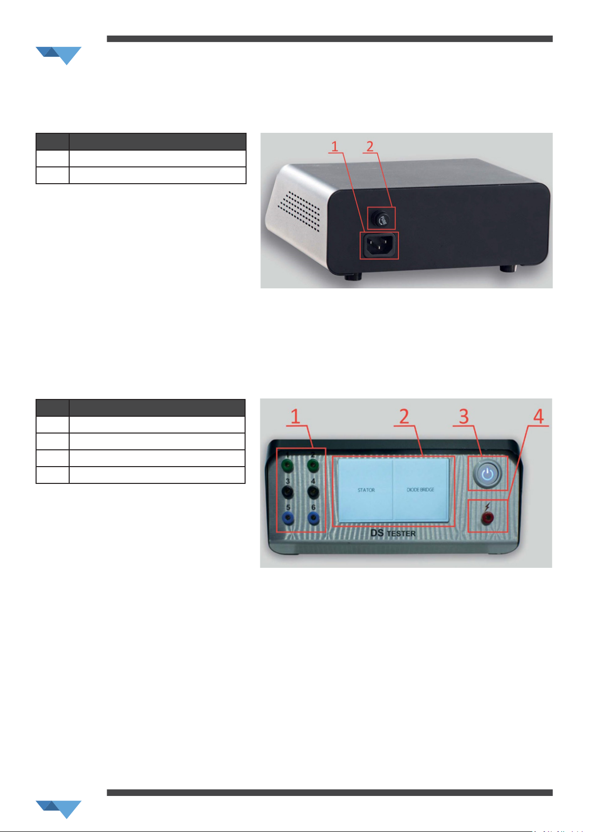
2.2 Front panel:
No. Descripon
1Connecon ports (6)
2LCD touch screen
3Power buon
4Connecon port test pen
No. Descripon
1Cable connecon
2Fuse (2A)
2.1 Back panel:
Plug the supplied power cable into the 12V
socket of the tester (1).
Check if the fuse is ghtened proparly.
If the fuse need to be replaced, turn it
counter clock wise to remove it from the
tester.
Plug the supplied test leads into the
connecon ports of the tester (1).
Please note that the number of test leads
should be equal to the number of phases.
Unnecessary connecon of addional test
cables may interfere with the test.
Plug the supplied test pen into the
connecon port on the right side of the
tester (4).
To start the tester, press the power buon.
Motoplat ®
Page 6

3.0 General informaon:
A stator is a xed element of an alternator that
consists of a magnecally conducve core with circular
mounted coil windings. By rotang the stator, the
rotor generates alternang current. The frequency
of generated alternang current equals the rotor
frequency, mulplied by the number of poles (usually
6).
Descripon of an alternator stator winding
1Winding terminals, phases: А, В, С;
2Stator winding
3Magnecally conducve core
Secon 3 – Alternator Stator Test
A three-phase stator winding consists of three
separate windings that are coiled in a certain order
on the magnec core. The phases in the windings are
displaced by one third (120 degrees) of a period of 360
degrees.
Motoplat ®
Page 7

Phase windings can be connected in a ‘delta’ or ‘star’ diagram. The windings are placed into a frame of steel
slots (stator core) to conduct magnec current from the rotor to the stator windings directly and to reduce
area dispersion of the magnec eld. The magnec eld is created in the coils and stator core.
Several types of stator windings are presented below:
Windings with a delta connecon Windings with a star connecon
Windings with a star connecon and center point Windings with a star and delta connecon with
jumpers in the alternator diode bridge
Motoplat ®
Page 8

3.1 Common failures:
Inter-turn fault (single-phase short circuit):
A. Alternator overload – When the alternator current exceeds the limit, the stator windings can be
overheated and this can cause damage to the winding insulaon.
B. Short circuit due to mechanical damage of the stator.
C. Manufacturing defect, mostly due to incorrect applying of the windings.
D. Incorrect use and storage of an alternator may cause moisture ingress into the unit, which may
lead to inter-turn fault as well.
Inter-phase fault (short circuit between phases):
Inter-phase faults may be caused by the same reasons as inter-turn faults.
Open fault of one or several windings:
Mechanical damage and/or corrosion caused by moisture, may be the reason for breakage of the
windings.
Phase to magnec core fault:
Phase to magnec core faults may be caused by the same reasons as inter-turn faults.
Motoplat ®
Page 9

3.2 Scan:
Start the tester by pressing the power buon and
select ‘STATOR’
Connect the test leads with the alligator clips to the
phases of the stator. It doesn’t maer which phase
is connected to which connecon port, as the tester
detects the connected windings automacally.
Press on ‘Scan’ at the right side of the screen.
The tester starts to detect the number of connected
windings.
In the example on the right, the connecon ports 1,
4 and 5 were used.
In case the stator has 6 outputs (star or delta
connecons, commutang to the alternator diode
bridge), connect 6 cables and press Scan. The tester
detects the number of connected windings which
will be displayed on the screen as the example on
the right:
When the phases are too close to each other, the
tester will show the following nocaon: “Too
many connecons”.
This means the phases are not connected the right
way or that the windings contains breakage.
(Please always check if the test leads are connected
the right way (1 test lead per phase) and if the
alligator clips don’t touch each other).
Motoplat ®
Page 10
Table of contents
Other Motoplat Test Equipment manuals


