MIDIbox Pedal Box User manual

2020/10/14 01:02 1/16 Introduction
MIDIbox - http://www.midibox.org/dokuwiki/
Introduction
The Pedal Box was built to be a very basic extension to a floorboard. Giving it an extra 8 Expression
Pedals, and a display to see patch change / CC names, as well as their values. It has grown far beyond
it's original intention.
Pedal Box
Is an expression pedal controller to expand an existing floorboard.
In addition to adding up to 8 expression pedals, up to 8 relays can be triggered and the LCD display
reflects the actions of your existing floorboard as well.
Pedal Board
Expanding into Pedal Board - you
can build a complete MIOS Powered

Last update: 2014/01/19 10:10 pedal_box http://www.midibox.org/dokuwiki/doku.php?id=pedal_box
http://www.midibox.org/dokuwiki/ Printed on 2020/10/14 01:02
Floorboard.
Is a complete MIOS/MBHP powered floorboard. It can support up to 16 buttons, with banks so there is
up to 128 virtual buttons.
No matter how many buttons you connect, you can always access all 128 virtual buttons
It also supports another 16 fixed buttons, that are the same regardless of bank. Great for boost, or
effect on/off functions. A further 2 special function buttons allow bank up/down and special functions.
Up to 8 relay's can be triggered and of course up to 8 expression pedals.
Each button or pedal can be assigned to a specific device, up to 7 devices can be controlled over 7
midi channels.
Pedal Box / Pedal Board features an extensive display system;
Program changes can be named, controls can be named, and can also display on/off, a meter showing
approximate position for pedals. It can display tap tempo rate, or even the name of a value for a
control - eg. For an Amp model select CC, it can display the model name selected.
Features
Expression Pedals
Up to 8 Expression Pedals or Pedal inputs (CV / 10k pot)
Individual option for pedals to be 'dynamic' by changing the midi messages sent based on
the Rig COntrol Patch Change
Value scaled between pre-defined min and max values (can also be different for each
program change)
A MIDI CC can be configured to act exactly as if it were connected to an analogue in (The
8 limit still applies)
LCD Display
Named Program Changes
Named CC events
Bar Graph displaying value/on/off
up to 10 specific CC value name tables for effect selection, etc
Tap Tempo BPM display
Pedal Board mode (max 34 buttons) - Optional
Up to 16 fixed midi output buttons with LED indicators
Up to 16 banked buttons for up to 128 midi commands with 16 LED indicators
Buttons toggle between a pre-defined min and max value
2 modes for buttons: switching or momentary
Bank displayed on 2×7 segment LED digits or LCD (use 2×20 screen for bank display on
LCD)
Bank Up / Down buttons
Multiple MIDI Devices
Can be setup to control up to 7 devices (1 bankstick required per device)
Each pedal or button has it's own device assignment
Rig Control
Internal patches allow up to 32 midi events can be sent at the same time giving you
complete control of all you gear
Patches can be triggered by any button (PbD only) or a MIDI IN event (PbX only)
Up to 8 relays can be used to switch amplifier channels, or other analog switch.
Relays can be triggered from patches, a button or a MIDI In event

2020/10/14 01:02 3/16 Introduction
MIDIbox - http://www.midibox.org/dokuwiki/
Gig Control
30 Song Lists can be setup to trigger patches in a given order
Up to 128 patches can be listed in any order
Cue Next / Cue Previous can be done from any button or a MIDI IN event
PedalSwap
Allows dynamic pedals to change there midi settings without utilizing Rig Control
PC Editor files allows easy…ish customization for different MIDI devices.
Settings configurable from box. (this is a very slow process but can you help you out in pinch,
it's far quicker to use the PC Editor).
What's The Difference?
Basically Pedal Box is a MIDI Monitor / Processor. Pedal Board is a… well… floorboard.
PbX PbD
Display MIDI Input Y Y
Push Buttons N Y
Bank functions N Y
Rig Control Via MIDI Y Y
Rig Control Via DIN N Y
Relay Control Via MIDI Y Y
Relay Control Via DIN N Y
Gig Control Via MIDI Y Y
Gig Control Via DIN N Y
PedalSwap Via MIDI Y Y
PedalSwap Via DIN N Y
Setup Via MIDI Y Y
Setup Via DIN N Y
External Pedal Input Y Y
MIDI Merger Y Y
* - Setup can still be done via the PC Editor and uploaded via MIDI
LCD Display

Last update: 2014/01/19 10:10 pedal_box http://www.midibox.org/dokuwiki/doku.php?id=pedal_box
http://www.midibox.org/dokuwiki/ Printed on 2020/10/14 01:02
Here are some examples of what is displayed on the LCD.
Program changes
Controllers
Controllers
Controllers
Controllers
On/Off controls
Tap Tempo Display
Setup Examples
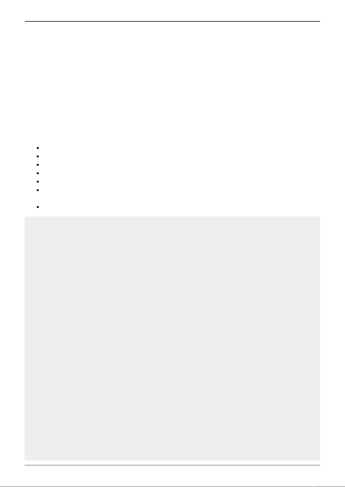
Pedal Box

2020/10/14 01:02 5/16 Introduction
MIDIbox - http://www.midibox.org/dokuwiki/
P
e
d
a
l
B
o
x
expands your existing floorboard with
functionality very similar to Pedal
Board
Up to 8 Expression pedals and 8 relays
can be used. Your floorboard provides
the buttons.
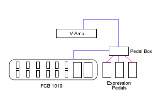
Extreme
P
e
d
a
l
B
o
a
r
d
(
a
n
d
Pedal Box) can taken to the extreme. Controlling up
to 7 MIDI devices.
Utilising Rig Control it can set them all to your
desired settings with a single stomp.
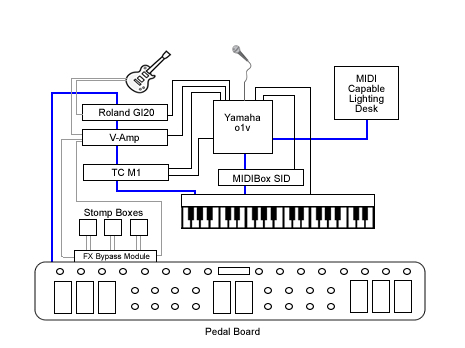
Pedal Board
P
e
d
a
l
B
o
ard can be used as a simple
customised floorboard with many
advanced functions.

Last update: 2014/01/19 10:10 pedal_box http://www.midibox.org/dokuwiki/doku.php?id=pedal_box
http://www.midibox.org/dokuwiki/ Printed on 2020/10/14 01:02
Manual
The Complete Usage Manual
Help can be found in the Pedal Box forum thread
Building Pedal Box / Pedal Board
Software
Pedal Box / Pedal Board has been written in C for PIC18F4620.
The legacy version for the PIC18F452 is no longer available.
Current Limitations
No Sysex Support
Installing
Firstly your PIC must be setup with bootloader and MIOS 1.9 or higher.
You should be familiar with compliling 'C' files for MIOS.
As well as uploading files to the Core module. See http://www.ucapps.de/
You need to upload the PB software, as well as fill the banksticks with the required info.
The first bankstick is used by PB with info about itself (Master Bankstick), the others are used to tell
PB info about the devices it is controlling (Device Banksticks).
USE THE PC EDITOR to setup and upload the Master Bankstick data.
You can also see the manual for more information.
Uploading device information
Device Banksticks tell PB about the MIDI devices it is controlling
In these banksticks:
The device name
The default MIDI channel

2020/10/14 01:02 7/16 Introduction
MIDIbox - http://www.midibox.org/dokuwiki/
The Event Map
MIDI event name and event type
128 Entries of CC's, 128 of Program Changes
10 x Parameter 2 value maps
Value name and associated value
Up to 128 entries each (1 for each value, does not need all entries)
USE THE PC EDITOR to setup and upload Device Bankstick data.
Uploading Pedal Box / Pedal Board
Now we are ready to upload Pedal Box. Browse to your Pedal Box directory and open the pbx_config.h
file.
You need to customise the application here. Comments inside in main.h will tell you what each setting
does.
Once you've customised the application it needs to be recompiled. Simply run re-make.bat.
Upload the created project.hex using MIOS Studio (or .syx using MIDI-OX or other midi software) file to
the core module. MIOS will now reboot, and that's it!
pbx_config.h in detail
PEDALBOARD - Set to 1 if for Pedalboard mode, or 0 for Pedalbox mode
ENABLE_MIDI_IN - If you wish to utilise the MIDI IN port, set to 1. Otherwise 0
MIDI_MERGER - To forward events recieved at the MIDI input to the output, set to 1. Otherwise 0.
MIDI_MERGER_DISABLE_MASTER - If the MIDI Merger is enabled, but you do not want to forward
messages targeting functions of PB (eg. A patch change) - set to 1. Otherwise set to 0 to forward all
messages.
AIN_DEADBAND - (standard MIOS question)
AIN_NUMBER_INPUTS - (standard MIOS question)
DIN_DEBOUNCE_VALUE - (standard MIOS question)
DIN_FIXED_BUTTONS - How many fixed or static footswitches are connected (0-16)
DIN_BANKED_BUTTONS - How many banked or dynamic footswitches are connected (1-16)
DIN_BANK_UP - The pin number assigned for bank up (2-33)
DIN_BANK_DOWN - The pin number assigned for bank down (2-33)
FIRST_PEDALSWAP_DIN_PIN - The pin assigned to the fist PedalSwap footswitch and LED Be wary
that placement does not interfere with Relays or LED Digit DOUT pins
NUM_PEDALSWAP_BUTTONS - Number of PedalSwap slots available (max and default = 6)
EVENT_SETUP_DIN_PIN - The pin number assigned for entering event setup mode (while holding
bank down) (0-31) Can not be the same as bank up or down
GLOBAL_SETUP_DIN_PIN - The pin number assigned for entering global setup mode (while holding
bank down) (0-31) Can not be the same as bank up or down
RELAY_SHIFT_REGISTER - If your using relays, which SR are they connected to if using SOME LED
Last update: 2014/01/19 10:10 pedal_box http://www.midibox.org/dokuwiki/doku.php?id=pedal_box
http://www.midibox.org/dokuwiki/ Printed on 2020/10/14 01:02
indicators, chosen SR must be after ALL POSSIBLE indicators
RELAY_LED_SHIFT_REGISTER - If your using LED indicators for relays, which SR are they connected
to SR should be AFTER the relay SR
USE_LED_INDICATORS - Are you using LED indicators for each footswitch, set 1 for yes, 0 for no
DIGITS_CONNECTED - Numver of LED digits connected (0-2). Set 0 for none.
DOUT_DIGITS_SR - Which SR is the first digit connected to.
Example of pbx_config.h setup
This is an example configured for:
4 expresson pedals, 8 fixed footswitches and 8 banked footswitches.
There are 1 LED digit connected to shift register 3 (start at pin 25).
There will also be 16 LED indicators for the footswitches .
Bank down is at pin 16, bank up at pin 17.
Special buttons for setup modes are the same as the first 2 fixed buttons.
PedalSwap is activated py footswitches connected to pins 19 -24 (LED's on counterpart dout
pins).
Relays are located on Shift Register 4 (pin 32), and it's led indicators are on SR 5 (pin 40)
///////////////////////////////////////////////////////////////////////////
// Configuration Parameters
//
///////////////////////////////////////////////////////////////////////////
/* General Settings */
#define PEDALBOARD 1 // 1 = Pedal Board mode 0 = Pedal Box
mode
#define ENABLE_MIDI_IN 1 // 1 = yes 0 = no
#define MIDI_MERGER 0 // 0 = off 1 = on
#define MIDI_MERGER_DISABLE_MASTER 1 // 0 = disabled 1 = enabled - If
set will disable forwarding of events on the master bankstick channel
/* Pedal Settings */
#define AIN_DEADBAND 7 // 7 for 7-bit midi is best
#define AIN_NUMBER_INPUTS 4 // 1 - 8 - number of pots connected
/* Pedal Board Buttons */
#define DIN_DEBOUNCE_VALUE 20 // debounce value
// FIXED BUTTONS MUST CONNECT FIRST
#define DIN_FIXED_BUTTONS 8 // 0-16 buttons that always stay the
same, regardless of bank

2020/10/14 01:02 9/16 Introduction
MIDIbox - http://www.midibox.org/dokuwiki/
// BANKED BUTTONS MUST BE CONNECTED AFTER FIXED BUTTONS
#define DIN_BANKED_BUTTONS 8 // 0-16 buttons that change with bank. 1
banked button will cause display errors when bank is over 99
//THESE SPECIAL FUNCTION BUTTONS MUST BE CONNECTED AFTER THE BANKED
BUTTONS!!!!!!!
#define DIN_BANK_UP 17 // 2 - 33, pin number of button used
to bank up
#define DIN_BANK_DOWN 16 // 2 - 33, pin number of button used
to bank down
#define FIRST_PEDALSWAP_DIN_PIN 18 // 4 - 33, First PedalSwap DIN pin
(others will be next higher sequentially)
// Must be higher than Bank Up and Down
// Be careful not to set the same in the space of LED
Digits or Relays
// Best place is next to the bank up/down pins
#define NUM_PEDALSWAP_BUTTONS 6 // 0-6, Number of PedalSwap Buttons
connected
// if you wish to have access to all 6 via MIDI (with
less than 6 buttons connected
// - please set to 6 and leave the DIN pins free
// THESE SPECIAL BUTTONS CAN BE ANY BUTTON CONNECTED, THEY ARE DUAL USE.
#define EVENT_SETUP_DIN_PIN 0 // 0 - 33, pin number of button used to
enter event setup
#define GLOBAL_SETUP_DIN_PIN 1 // 0 - 33, pin number of button used to
enter AIN setup
/* Relay setup */
#define RELAY_SHIFT_REGISTER 4 // 0 - 7 Relay's Shift Register
#define RELAY_LED_SHIFT_REGISTER 5 // 0 - 7 Relay's LD indicator Shift
Register
/* LED setup */
#define USE_LED_INDICATORS 1 // Enable LED indicators connected 1 =
Enabled 0 = Disabled
/* LED Digit Setup */
#define DIGITS_CONNECTED 1 // 0-2 How many LED digits are connected
#define DOUT_DIGITS_SR 3 // What SR do the digits start from.
// 2nd digit will be on the next SR
////////////////////////////////////
// IF NO LED DIGITS ARE CONNECTED //
// A 2x20 LCD DISPLAY CAN BE USED //
// WITH THE BANK DISPLAYED ON THE //
// LAST 4 CHARACTERS //
////////////////////////////////////

Last update: 2014/01/19 10:10 pedal_box http://www.midibox.org/dokuwiki/doku.php?id=pedal_box
http://www.midibox.org/dokuwiki/ Printed on 2020/10/14 01:02
Download
Application
For PIC18F4620
Pedal Box / Pedal Board v2.6beta1
Device Bankstick Downloads
Behringer V-Amp Series
PC Editor
Pedal Board Editor 2 v1.0
Please note the editor requires a minimum
of WinXP with .Net 3.5
Docs
The Complete Usage Manual
Known Bugs
Version 2.6:
Possble issues with LED's not lighting up correctly
(minor) Tap Tempo LED only fuctions when another led is lit up… cool huh?
Please report bugs in the Pedal Box forum thread
History
* 2.6beta1
Fixed critcal rig control bug
Fixed lagging with MIDI input while in Pedal Board mode. (May have wrecked led indicators in
the process though)
Relays can now be labeled and polarity set from the PB Editor software
Reduced max cuelists to 20
Added MIDI as AIN feature - allows a recieved CC to be translated as if it were an analogue input
Added PedalSwap feature - temporarily change the settings of expression pedals
* 2.5beta3
Other manuals for Pedal Box
1
Table of contents
Other MIDIbox Music Pedal manuals


