Micron Micromax User manual
Instruction manual
Bromyard Industrial Estate, Bromyard,
Herefordshire, HR7 4HS, UK
Tel: + 44 ( ) 1885 482397
Fax: + 44 ( ) 1885 483 43
E-mail: enq[email protected].uk
URL: http://www.micron.co.uk


3
CONTENTS
This manual contains all the information required to ensure successful and
safe application of agrochemicals using sprayers fitted with one or more
MICROMAX atomisers. It should be treated as an integral part of the
machine and made easily a ailable to the spray operator for reference, as
required, during the spraying operation.
Full instructions for the efficient, effecti e and safe operation of
MICROMAX atomisers are included in this olume, along with all
necessary information for installation, maintenance and repair. Reference
may also be required to the spray ehicle and/or base sprayer handbooks.
MICROMAX CONTENTS
THE SPECIFICATIONS QUOTED ARE CORRECT AT THE TIME OF GOING TO PRINT.
THE RIGHT IS RESERVED TO VARY SPECIFICATIONS WITHOUT NOTICE.
DUE CARE HAS BEEN TAKEN IN THE PREPARATION OF THIS MANUAL. NO
LIABILITY, ABOVE THAT REQUIRED BY APPLICABLE LAWS, WILL BE ACCEPTED
FOR INJURY, LOSS OR DAMAGE DUE TO OMISSIONS OR MISTAKES.
REPRODUCTION OF THIS MANUAL, IN PART OR IN WHOLE, IS ONLY PERMITTED
WITH PRIOR WRITTEN CONSENT.
© MICRON SPRAYERS LIMITED 2002 – ALL RIGHTS RESERVED
SECTION PAGE
1Description.........................................................................4
2 Specification.......................................................................5
3 Ten key points for users......................................................6
4 Safety and the en ironment ...............................................7
5 Installation..........................................................................8
6 Basics of Controlled Droplet Application (CDA)................24
7 Calibration and adjustment ..............................................34
8 Operation.........................................................................48
9 Maintenance ....................................................................55
10 Trouble shooting ..............................................................59
11 Parts list and diagram.......................................................60
12 Notes on units and useful con ersions ..............................62
13 EC Declaration of Incorporation.......................................63
14 User notes ........................................................................64

4
1 – DESCRIPTION
ROTARY ATOMISER FOR VEHICLE MOUNTED SPRAYING
The ehicle-mounted MICROMAX is a spinning disc rotary atomiser
designed for the Controlled Droplet Application (see section 6 ‘Basics of
Controlled Droplet Application’) of most agrochemicals. By efficiently
producing only the spray droplet sizes appropriate for the particular
application the MICROMAX cuts spray olumes and costs and minimises
any risk of en ironmental contamination.
The unique design of the electrically dri en MICROMAX ensures
controlled spray atomisation o er a wide range of liquid feed rates and
gi es a choice of three disc rotational speeds, and thus spray droplet sizes,
to suit different applications:
200 μm to 500 μm spray droplets for pre-emergent and post-emergent
herbicide applications where drift a oidance is essential.
100 μm to 300 μm spray droplets for most post-emergent herbicides,
defoliants, foliar feeds and fungicides to ensure good co erage of plant
surfaces while minimising any risk of uncontrolled spray drift.
75μm to 150μm spray droplets for insecticides and fungicides.
The MICROMAX is designed primarily for use in agriculture, the materials
used in its construction will withstand all standard products used for
con entional agricultural spraying. The MICROMAX can be used with
both water and oil based sprays, but is not designed for use with liquid
fertilisers or unusually aggressi e, dense, or iscous products.
The low application olumes allowed by the MICROMAX mean greater
areas can be sprayed per tank load (or lighter ehicles used), with
dramatic sa ings in the cost, time and effort of the spraying operation.
This both speeds up the spraying process and allows more spraying days,
thus allowing quick and cost-effecti e pesticide application to be
undertaken when needed.
The MICROMAX is dri en by a 12 DC electric motor, allowing it to be
powered by the ehicle's electrical system. Disc rotational speed, and
therefore droplet size, is selected using the three gear belt and pulley dri e
system. Standard plumbing can be used.
1 – DESCRIPTION MICROMAX

5
2 – SPECIFICATION
Figure 1 – MICROMAX S ray Head
Table A – Ty ical Performance Data
Height 230 mm
(9 inches)
Disc
Diameter
125 mm
(5 inches)
Weight 1 kg
(2.2 pounds)
Power
Su ly 12 DC
Current
Drawn3A max
Power
Used 36W max
MOUNTING
BRACKET
LIQUID
FEED
NOZZLES
MOTOR
BELT AND
PULLEY DRIVE
ATOMISER
DISC
Low Medium High
Feed Rate 0.5 - 3 l/min
1 - 6.5 US pt/min
0.25 - 1 l/min
0.5 - 2 US pt/min
0.125 - 0.5 l/min
0.25 - 1 US pt/min
Disc S eed 2000 rpm 3500 rpm 5000 rpm
A lication
Volume
30 - 200 l/ha
3 - 21 US gpa
20 - 80 l/ha
2 - 8.5 US gpa
10 - 40 l/ha
1 - 4 US gpa
Dro let Size 200 - 500 μm 100 - 300 μm 75 – 150 μm
S eed Setting
MICROMAX 2 – SPECIFICATION

6
3 – TEN KEY POINTS FOR USERS
The following list is intended to be referred to prior to commencing each
spraying operation, to remind users of the key points for the safe and
efficient use of the MICROMAX atomiser.
1SAFETY: Always refer to the product label for specific
recommendations for each product, and to Section 4 ‘Safety and
En ironmental Considerations’ before commencing any spraying
operation.
2 Check that all atomisers rotate freely. If binding or roughness is felt,
inspect the motor, belt dri e and disc bearings.
3 Check that the pulleys and belts are clean and free from damage
and that the appropriate gear is selected, see Section 7 ’Calibration
and Adjustment’.
4 Check that the atomiser discs are secure and free from damage or
blockage by dried chemical.
5 Ensure that the atomisers are securely and correctly positioned on
the boom or support structure, and are set to the correct distance
from the crop/target to be sprayed, see Section 5 ‘Installation’.
6 Inspect the entire sprayer for damaged or twisted hoses, leaks in the
chemical system, or damaged wires.
7 Check that the correct nozzles and flow restrictor orifices are fitted,
and that the correct system pressure is set to pro ide the required
liquid feed rate, see Section 7 ‘Calibration and Adjustment’.
8 Turn the atomiser motors on, to ensure they are rotating and at the
correct speed, see Section 7 ‘ Calibration and Adjustment’.
9 Whilst spraying, isually ensure that each atomiser is working, and
erify the accuracy of the calibration of the sprayer by checking the
olume of liquid used against the area being sprayed.
10 After use, always flush out the entire system with clean water or a
suitable sol ent. Never lea e chemical residues in the tank or pipe
work. Wash off outer surfaces of atomisers, booms, etc. to a oid
build up of pesticide residues.
3 – TEN KEY POINTS FOR USERS MICROMAX

7
4 – SAFETY AND THE ENVIRONMENT
Using agrochemicals is a hazardous process. Operators should be
familiar, and comply, with all rele ant legislation and/or regulations.
Keep people and animals out of areas being sprayed. Obser e all
regulations on spraying near inhabited or public areas and waterways.
Never use MICROMAXs in potentially explosi e atmospheres, or spray
flammable liquids, mixtures of incompatible chemicals, suspended
insoluble particles, or anything other than agrochemicals through them.
Always read the product label carefully to disco er:
recommended application rate and dilution
operator protection required
necessary en ironmental protection measures
action required in case of accidental spill,
ingestion, skin or eye contact
Never eat, drink, or smoke when working with agrochemicals.
Always store agrochemicals safely to protect people and animals, and to
safeguard the en ironment. Wash and rinse chemical product containers
well using proper equipment. Make a hole in the bottom of empty
containers to pre ent re-use. Dispose of containers, unused
agrochemicals, and washing residues in accordance with regulations.
4.1 OPERATOR PROTECTION
Always wear the protecti e clothing items listed on the product label for
mixing and filling. After using agrochemicals or handling equipment
always wash your hands and clothes thoroughly.
The minimum protecti e clothing required for spraying with the
MICROMAX from an uncabbed ehicle, or of cleaning contaminated
atomisers and sprayers is:
rubber glo es
boots/shoes & long trousers
eye protection
long slee ed shirt
MICROMAX 4 – SAFETY AND THE ENVIRONMENT
8
5 – INSTALLATION
The design of a sprayer incorporating one or more MICROMAX atomisers
will ary according to the crop or target to be sprayed.
This section gi es general ad ice and design data but is not intended to
pro ide specific instructions for building e ery type of sprayer. Original
Equipment Manufacturers (OEMs) should contact Micron if they require
any further information for a particular application.
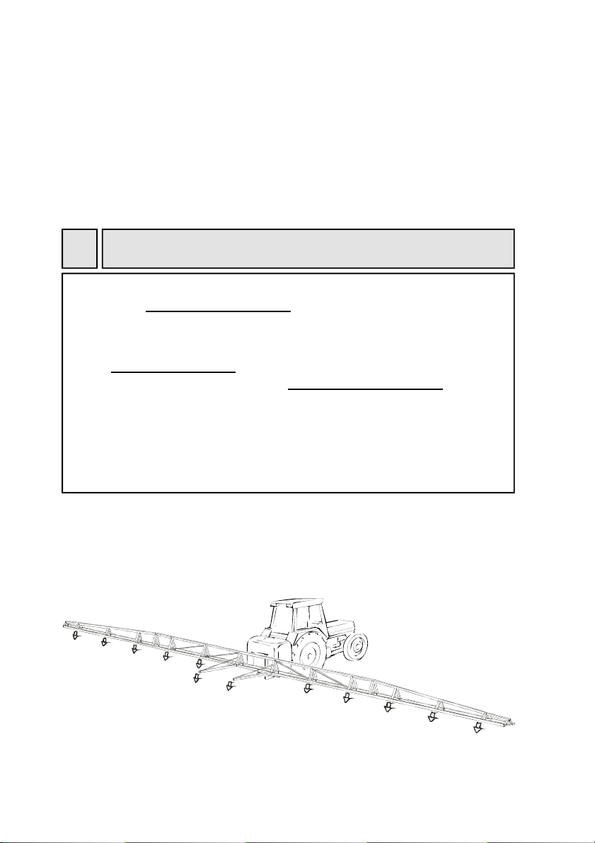
Figure 2 – A boom s rayer for field cro s
5.1 MOUNTING THE MICROMAX
5.1.1 Some ty ical configurations
The design of agricultural equipment is best done by a qualified
and com etent engineer. All rele ant legislation and
regulations should be adhered to.
Agricultural equipment should only be worked on by suitably
trained ersonnel. Manufacture and assembly work should
be completed by trained and com etent technicians.
Ensure that all welds are sound, and that all fasteners used are
correctly tightened.
Use the correct tools for the job to a oid injury or damage.
Use safe lifting methods when mo ing hea y components.
IMPORTANT SAFETY RECOMMENDATIONS
!
5 – INSTALLATION MICROMAX

9
Figure 3 – A boom s rayer for orchard floors
Figure 4 – An ATV s rayer for orchard floors, grassland, etc.
5.1.2 Strength and rigidity
Support arms or frameworks should be of strong and rigid construction.
Spray booms should also be rigid, and preferably pro ided with
suspension. If the boom is lightweight in construction, it is ad isable to
reinforce and stabilise it.
Excessi e bouncing will cause une en spray output from the MICROMAX.
Brace bars, nylon support ropes and springs are common methods of
reducing boom bounce.
5.1.3 Folding booms
If mounting MICROMAX atomisers on a folding boom, it is essential to
ensure that the atomisers are positioned such that they do not interfere
with the folding mechanism.
MICROMAX 5 – INSTALLATION

10
If mounting MICROMAXs on a spray boom, one or more extension arms
may be required to pro ide the necessary clearance from the sprayer,
support wheels, or other obstructions. These arms can be constructed
from hea y gauge 40 mm (1.5 inch) or larger angle iron, channel, tube or
box section. They should be constructed and mounted so as to be as rigid
as practicable, to minimise bounce.
5.1.4 S ray attern clearance
The MICROMAX produces a large hollow cone spray pattern, arying in
diameter with different atomiser speeds/droplet sizes. Support arms or
frameworks should be designed to allow a radial clearance of 1.2m (4
feet) to pre ent spray pattern disruption.
Figure 5 – S ray attern clearance
Figure 6 – S rayer clearance
EXTENSION ARMS
MICROMAXSPRAY PATTERN
BOOM
1.2m (4 feet)
CLEARANCE RADIUS
5 – INSTALLATION MICROMAX
Table of contents


