MG STE02W User manual

Serial to Ethernet Converter
STE02W
USER MANUAL
V. 1.2

2
INDEX
1
Introduction 4
1.1
Declaration of conformity 4
1.2
Package Contents 4
1.3
Technical Characteristics 4
2
Description 5
3
Hardware Specifications 6
3.1
Connections 6
3.1.1
Front Panel 6
3.1.2
Rear Panel 7
4
Installation 8
4.1
Hardware Connection 8
4.1.1
Connecting to the Wireless network 8
4.1.2
Connecting a serial device 9
4.1.3
Connection to Power Line 9
4.1.4
Sample Configuration 10
4.2
Configuration Software 11
4.2.1
Software Installation 11
4.2.2
Configuring device with ‘MG Device Wiz’ 13
4.3
Advanced Configuration 20
4.3.1
System Information 21
4.3.2
Serial Port – Basic 22
4.3.3
Serial Port – Port Services 23
4.3.4
Serial Port – Advanced 25
4.3.5
Serial Port – Statistics 25
4.3.6
Network – Basic 26
4.3.7
Network – Wireless 27
4.3.8
Network – Wireless Security 28
4.3.9
Network – Network Services 29
4.3.10
Alarms 30
4.3.11
Backup/Restore 32
4.3.12
Reboot 33

3
5
Operating mode examples 34
5.1
Realport 34
5.1.1
STE02W Configuration 34
5.1.2
Driver Installation 34
5.1.3
System Testing 34
5.2
Serial Bridge 35
5.2.1
STE02W Configuration 35
5.2.2
System Testing 35
6
Reset Procedure 36
7
Technical Support 38

4
1 Introduction
The contents of this manual may change without notice. MG S.r.l. assumes no
responsibility for errors and/or omissions technicians.
1.1 Declaration of conformity
With the present MG S.r.l. declares that the product STE02W is in compliance with the
essential requirements and other relevant provisions of Directive 1999/05/EC, with
reference to the following regulatory standards:
EN55022
EN55024
EN61000-3-2
EN60950
FCC ID: MCQ-50M880
1.2 Package Contents
−STE02W module.
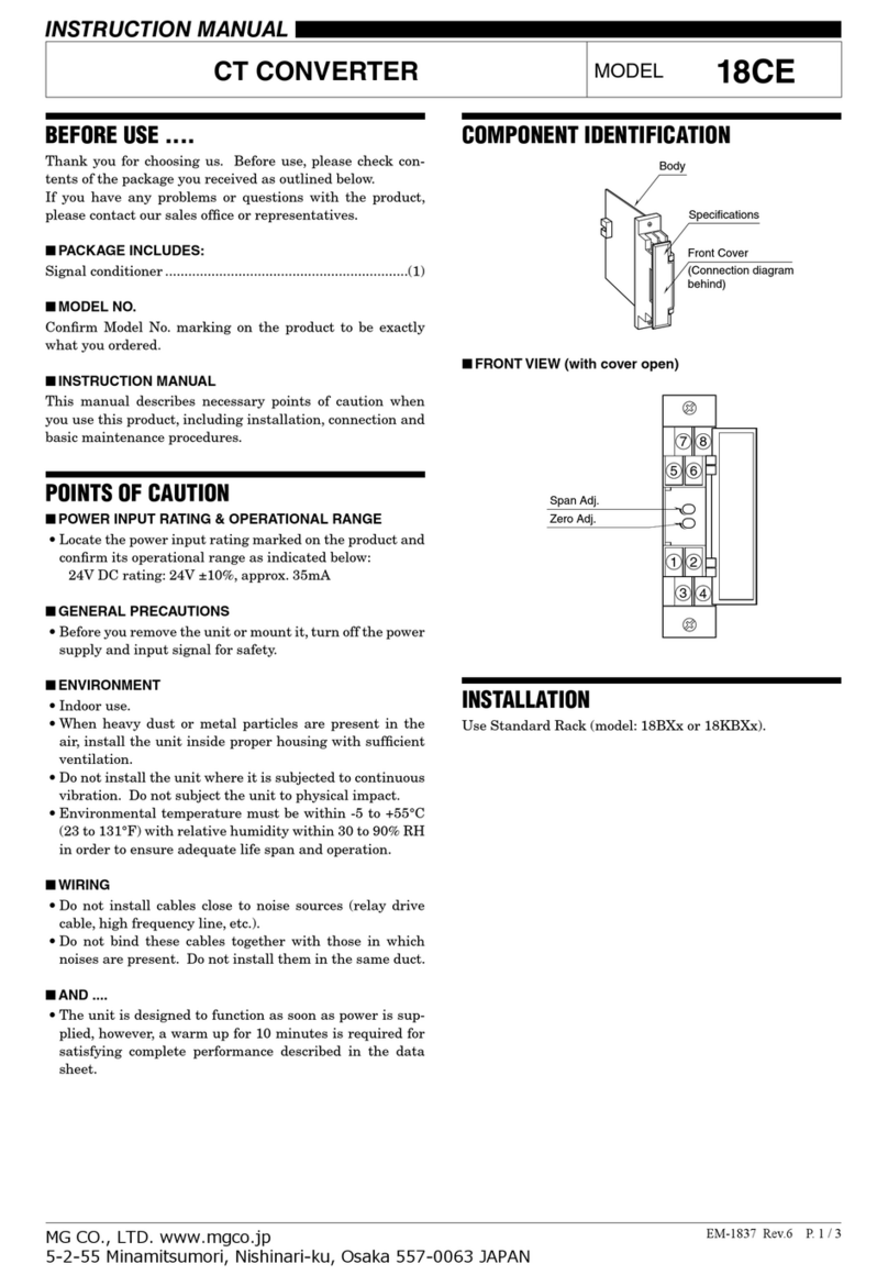
−Antenna.
−AC Power Adapter, 12V (optional).
−Utility and installation CD.
1.3 Technical Characteristics
−Supported Protocols: IP, TCP, UDP, DHCP, SNMP, SSL/TLS, Telnet, LPD, http,
HTTPS, SMTP, ICMP, IGMP, ARP, ADDP.
−Server and Client operating mode.
−Wireless LAN: 802.11b up to 11Mbps with data encryption type WEP/WEP2.
Possibility to connect to infrastructure networks and ad-hoc networks.
−Serial Port: from 50 to 230 Kbps.
−Supported Serial Signals: TXD, RXD, RTS, CTS, DTR, DSR.
−Data format: 5-6-7-8 bit; parity even, odd, mark, space.
−1-2 stop bits.
−Flow Control: XON/XOFF, RTS/CTS.
−Sending alert e-mail (SMTP) on recognition of serial signals state.
−Alert e-mail (SMTP) on character recognition.
−Sending repeated e-mails on persistence alarm.
−Consumption: 1,5 W.
−Led: Power, Link, Activity.
−Operating Temperature: from -20 to +60°C.
−Humidity: from 5% to 90% not condensing.
−Power Supply: 5-30 Vcc with external adapter.

5
2 Description
STE02W is a device that allows the transfer of a serial port through a wireless network or,
more generally, through an Internet connection.
It has a RS-232 serial port on DB9 connector that can be connected to different types of
serial devices (e.g. PLCs, controllers, keypad security, access control devices, etc.) and it
can send e-mail messages when an alarm condition occurs.
You can also interact remotely, connecting via Internet to the STE02W with a browser, to
check the status and information of your serial device.
To meet different needs, you can set the speed of serial interface, the parity bits, and stop,
the format of the data and the type of flow control; this way you can adapt STE02W to your
application quickly and easily.
STE02W is designed to work in different applications being able to handle, in addition to
connecting to a PC, even communication between two serial devices networked through
both STE02W. Main operating modes are: Real Port, Serial Bridge, TCP Socket, UDP
Socket, Modem Emulation.
Furthermore, it can be supplied with an extended range of voltages, through the
appropriate pin on terminal block.
Figure 1: STE02W connected to a serial device and a PC.
Serial
Ethernet
Access Point
Serial Device
WLAN

6
3 Hardware Specifications
3.1 Connections
3.1.1 Front Panel
−Power Supply: Male connector.
Figure 2: Module STE02W: Front View.
Power Connector

7
3.1.2 Rear Panel
−Serial Port: DB9 male connector (DTE).
−Standard WiFi Antenna connector.
−Power Supply LED: STE02W device power state.
−Link LED: Wireless network Connection.
−Activity LED: Wireless connection Activity.
Figure 3: STE02W Module: Rear View.
Pin
Number
Signal
D
escription
Function
1 DCD Data Carrier Detect
2 RD Receive Data Data Input
3 TD Data Transmission Data Output
4 DTR Data Terminal
Ready
5 GND Ground
6 DSR Data Set Ready
7 RTS Request To Send
8 CTS Clear To Send
9 RI Ring Indicator
Figure 4: DB9 Serial Connector Pin Out.
Yellow Link LED Green Link LED
Antenna Connector
DB9 Serial Connector
Power Supply LED

8
4 Installation
4.1 Hardware Connection
4.1.1 Connecting to the Wireless network
Turn on the device and wait for the Link LED to stop blinking; this means that STE02W is
connected to one of the available wireless networks. The converter is able to connect to
networks with access point or ad-hoc networks. If the Link LED does not stop blinking,
make sure that the device is in an area covered by Wireless Lan or that the network
security features are compatible with the security settings of your STE02W.
Figure 5: STE02W: Network connection.
Access Point
WLAN

9
4.1.2 Connecting a serial device
Connect DB9 male connector of STE02W to serial device using RS-232 serial cable (DB9
M/F); if STE02W needs to be connected to a PC or another device with serial port DTE
use a NULL modem cable (DB9 F/F).
Figure 6: Link between STE02W and serial device.
4.1.3 Connection to Power Line
Connect the included power supply to power connector placed on back of device. Then
connect the power supply to power line.
Figure 7: STE02W Power Connection.
Serial Device

10
4.1.4 Sample Configuration
Figure 8: Sample Configuration.
Serial
Ethernet
Access Point
Serial Device
WLAN
Table of contents
Other MG Media Converter manuals