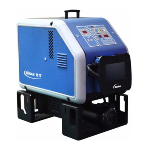
Meler MACRO 200 User manual

ADHESIVE
MELTER
MACRO 200
INSTRUCTIONS
MANUAL
MA-5068-ENG 221220
GLUING SOLUTIONS

Published by:
Focke Meler Gluing Solutions, S.A.
Pol. Arazuri-Orkoien, c/B, nº3 A
E-31170 Arazuri - Navarra - Spain
Phone: +34 948 351 110
info@meler.eu - www.meler.eu
Focke Group
Edition December 2020
© Copyright by Focke Meler
All rights reserved. Its reproduction, diffusion or use by electronic or other
means of all or any part of this document without the express authorization of
its owner is strictly prohibited.
The specifications and information contained in this manual may be modified
without prior notice.
The official language of this manual is only the English language. The
remaining versions of the manual in other languages are mere translations
without any official value or efficacy. In case of discrepancies or contradictions
between the English version of the manual and any other version of the manual
written in another language, the English version will prevail.

MA-5068-ENG MACRO 200 INSTRUCTIONS MANUALTABLE OF CONTENTS
TABLE OF CONTENTS
1. SAFETY GUIDELINES 1-1
General 1-1
Symbols 1-1
Mechanical components 1-2
Electrical components 1-2
Hydraulic components 1-2
Pneumatic components 1-2
Thermal components 1-3
Materials 1-3
Noise emission declaration 1-3
Intended use 1-4
Limited use 1-4
2. INTRODUCTION 2-1
Description 2-1
Intended use 2-1
Limited use 2-2
Modes of operation 2-2
Hot-melt melter identification 2-3
Main components 2-4
Control card components 2-6
Pumping control card components 2-7
Optional equipment 2-8
3. INSTALLATION 3-1
Introduction 3-1

FOCKE MELER GLUING SOLUTIONS TABLE OF CONTENTS
Installation requirements 3-1
Free space 3-1
Electrical consumption 3-2
Compressed air 3-2
Other factors 3-2
Unpacking 3-3
Contents 3-3
Mounting the equipment 3-3
Electrical power connection 3-3
Pneumatic connection 3-4
Hose and applicator connection 3-5
Parameter Programming 3-5
Programming working temperatures 3-5
Selecting the overheating value 3-6
Keeping a component on display 3-7
External I/O connections 3-7
Temperature ok 3-8
External Standby 3-8
Low level (optional) 3-9
Output inhibitor 3-9
Starting up the motor (ok ext) 3-10
Motor speed set point reference (ref ext) 3-10
Failures output in pump control card 3-11
4. MELTER OPERATION 4-1
General information 4-1
Filling the tank 4-1
Starting up the melter equipment 4-2
Melter equipment displays 4-3
Displaying the temperature for each component 4-4

MA-5068-ENG MACRO 200 INSTRUCTIONS MANUALTABLE OF CONTENTS
Alarm displays 4-5
Hot-melt display level (optional) 4-6
Display and adjustment of the working speed 4-6
Temperature adjustment 4-6
Programming the applicator parameters 4-7
Setting the clock 4-8
Programming the current day and hour 4-8
Programming equipment activation/deactivation 4-9
Disabling the equipment activation/deactivation program 4-10
Programming the equipment’s standby function activation/deactivation 4-11
Disabling the equipment standby function programming 4-12
Special function buttons 4-12
Pumping control 4-13
Starting up the pump control card 4-13
Pumping safety measures 4-14
Password security 4-15
LED indicators 4-15
Modes of operation 4-16
Mode of operation with internal pumping control and internal speed control 4-16
Mode of operation with internal pumping control and external speed control 4-17
Mode of operation with external pumping control and internal speed control 4-18
Mode of operation with external pumping control and external speed control 4-19
User configuration menu 4-21
Displaying alarms and reset function 4-21
Maximum rpm alarm 4-21
Minimum rpm alarm 4-22
Variator alarm 4-22
Configuring speed ramp 4-22
Programming speed ramp 4-23
Current Vin voltage display 4-24

FOCKE MELER GLUING SOLUTIONS TABLE OF CONTENTS
By-pass valve regulation 4-24
Manual valve control 4-25
Pneumatic valve control 4-25
Turning off the melting equipment 4-25
Additional temperature safety signal 4-26
5. MAINTENANCE 5-1
Equipment cleaning 5-1
Depressurizing the system 5-2
Filter maintenance 5-2
Pump filter 5-2
Tank filter 5-3
Cleaning the tank 5-4
Changing adhesive type 5-4
Cleaning burnt adhesive 5-4
Emptying the tank 5-5
Pump maintenance 5-6
Inspecting for leaks 5-6
Motor-gear maintenance 5-6
Cleaning the motor fan 5-6
Checking the lubricant 5-6
Recommended lubricants 5-7
Thermostats maintenance 5-7
6. TECHNICAL CHARACTERISTICS 6-1
General 6-1
Dimensions 6-2
Accessories 6-3
Pneumatic by-pass valve pressure control system 6-3
Light tower system 6-3

MA-5068-ENG MACRO 200 INSTRUCTIONS MANUALTABLE OF CONTENTS
Level control system 6-3
Automatic feeder system 6-3
7. ELECTRICAL DRAWINGS 7-1
8. PNEUMATIC DIAGRAM 8-1
Components list 8-1
By-pass valve pneumatic control system 8-1
9. SPARE PARTS LIST 9-1
A. COVER- TANK ASSEMBLY 9-2
B. SIMPLE/ DOUBLE DISTRIBUTOR ASSEMBLY 9-3
C. FILTER AND PRESSURE VALVE ASSEMBLY 9-4
D. GEARED MOTOR- PUMP ASSEMBLY 9-5
E. ELECTRICAL CABINET 9-6
A. PROFIBUS CONNECTION A-1
Profibus electrical connection A-1
Configuration table A-2
Memory table A-3
Memory table description A-5
Byte: Configuration – Read A-5
Byte: Configuration- Read/Write A-5
Byte: Operative elements A-6
Byte: Overtemperature alarms A-6
Byte: Broken sensor alarms A-7
Byte: Mode Motor A-8
Byte: Alarms Communication A-8
EC DECLARATION OF CONFORMITY 10-1

FOCKE MELER GLUING SOLUTIONS TABLE OF CONTENTS
This page is intentionally left blank.

SAFETY GUIDELINES
1-1
MA-5068-ENG MACRO 200 INSTRUCTIONS MANUAL
1. SAFETY GUIDELINES
General
The information contained in this section applies not only to everyday
equipment operation, but also to any procedure carried out on it, whether for
preventive maintenance or in the case of repairs and the replacement of worn
out parts.
It is very important to observe the safety warnings in this manual at all times.
Failure to do so may result in personal injury and/or damage to the equipment
or the rest of the installation.
Before beginning work on the equipment, read this manual carefully, and in
case of any doubt, contact our Technical Service Center. We are available for
any clarification that you might need.
Keep manuals in perfect condition and within reach of personnel that use the
equipment and perform maintenance on it.
Also provide necessary safety material: appropriate clothing, footwear, gloves
and safety glasses.
In all cases, observe local regulations regarding risk prevention and safety.
Symbols
The symbols used on both the melter/applicator equipment and in this manual
always represent the type of risk we are exposed to. Failure to abide by a
warning signal may result in personal injury and/or damage to the equipment
or the rest of the installation.
Warning: Risk of electrical shock. Carelessness may produce injury or death.
Warning: Hot zone with high temperatures. Risk of burns. Use thermal
protective equipment.
Warning: System under pressure. Risk of burns or particle projection. Use
thermal protective equipment and glasses.
Warning: Important information for the correct use of the system. May include
one or several of the previous hazards, and therefore must be kept in mind to
avoid damage and injury.
Warning: Dangerous area. Risk of entrapment. Carelessness may produce
injury or death.

FOCKE MELER GLUING SOLUTIONS
1-2
SAFETY GUIDELINES
Mechanical components
The hot-melt installation, which is installed to this device, requires moving
parts that can cause damage. Use the equipment correctly, and do not remove
the safety guards while the equipment is in operation; prevent the risk of
possible entrapment due to moving mechanical parts.
Do not use the equipment if the safety devices are not in place or appear to be
inadequately installed.
For maintenance or repair operations, stop the movement of moveable parts
by turning off the main switch.
The device has no moving mechanical parts, so it does not pose risks to
consider in this section.
Electrical components
The system works with single-phase or three-phase current of a certain
power. Never handle the equipment with the power connected, as this may
result in powerful electrical shocks.
The installation must be correctly grounded.
The installation’s power cable conductors must match the required electric
current and voltage.
Periodically inspect the cables to check for crushing, wear and tear, as well as
to prevent tripping and falls as a result of their placement.
Although the system meets EMC requirements, it is inadvisable to use
devices that transmit high levels of radiation, i.e., mobile phones or soldering
equipment in their vecinity.
Hydraulic components
As this is a pressurized system, precautions related to this type of equipment
must be observed.
Before each operation, always make sure that the adhesive circuit is
completely free of pressure. There is a high risk of hot particle projection,
along with the corresponding danger of burns.
Use caution with the residual pressure that may remain in the hoses when the
adhesive cools. When reheated, there is a risk of hot particle projection if the
outputs are left open.
Pneumatic components
Some equipment uses compressed air to 6 bar pressure. Before any
manipulation, please ensure that the circuit has lost fully air pressure. The
risk of projection of particles at high speed can cause injury to a certain
severity.
Extreme precautions with the residual pressure that could be contained in the
circuit, before disconnecting any pneumatic feeding tube.

Table of contents
Other Meler Melting Machine manuals
Popular Melting Machine manuals by other brands

Cole Parmer
Cole Parmer MP-400 Series instruction manual

CIMLINE
CIMLINE MATRIX 1500 Owner's/operator's manual

Graco
Graco THERM-O-FLOW T7 Series instructions

Nordson
Nordson AltaBlueA4TP Customer product manual

VALCO MELTON
VALCO MELTON D4-L user manual

Viega
Viega ProRadiant Basic Digital Snow Melt Control... Product instructions