Maverick 17 HPX-V 2014 User manual

Model year 2014! ! 1
Maverick Boat Company, Inc. • 3207 Industrial 29th St. • Fort Pierce,
Florida 34946 • (772)-465-0631 or (888)-shallow • Fax: (772) 489-2168
MAVERICK 17 HPX-V
Owner’s Manual
Dear New Boat Owner,
Welcome to the Maverick Family!
Thank you for choosing a Maverick boat to transport you to
your angling dreams. We believe the Maverick 17 HPX-V is the
best backcountry boat on the market, and we’re sure that you’ll be
completely satisfied with the unmatched performance, quality and
fishability of your new boat.
We value your input, not just at the time of the sale, but
throughout the entire boat ownership period, and we’ve taken
steps to allow you to share that information. Over the next year or
so, you will receive at least two questionnaires to fill out and
return.
Be sure to visit our website www.maverickboats.com to find
information on company events like our Owner’s Tournaments
and Corporate Calendar. You’ll find a wealth of information on our
Forum, where you can ask questions, get answers and join other
Maverick owners to discuss all applications of your boat. We’re
proud to have you as a member of the Maverick family!
Tight lines and screaming drags!
D. Scott Deal

Model year 2014! ! 2
Maverick Boat Company, Inc. • 3207 Industrial 29th St. • Fort Pierce,
Florida 34946 • (772)-465-0631 or (888)-shallow • Fax: (772) 489-2168
TABLE OF CONTENTS
17 HPX-V SPECIFICATIONS
L.O.A............................................................16’ 09”
BEAM..............................................................6’03”
DRAFT................................................................8”
WEIGHT W/ ENGINE............................1,150 LBS.
FUEL CAPACITY........................................24 GAL.
MAX H.P......................................................90 HP
MAX CAPACITIES........3 PERSONS OR 450 LBS
Maintenance and Cleaning..........................................................3
Engine Stop Switch......................................................................4
Fuel / Water Separators...............................................................5
Garboard Drain Plug....................................................................5
Gauges.........................................................................................6
Switch Panel................................................................................6
Boat Layout..................................................................................7
Ditty Bag.......................................................................................7
Aluminum Plate Locations............................................................8
Trolling Motor/Wiring System.......................................................9
Bilge System..............................................................................11
Props..........................................................................................12
Fuel System...............................................................................13
Self Bailing Cockpit....................................................................14
Livewell System.........................................................................14
Wiring System/Breakers and Fuses...........................................15
Battery Switch/Breaker Panel....................................................16
Gauge Upgrades........................................................................17
Saltwater Washdown.................................................................17
Optional Trim Tabs.....................................................................18
Optional Power Pole..................................................................19
Power Pole Aluminum Plate Locations......................................19
Optional Boarding Ladder..........................................................20
Optional Jackplate......................................................................20
Warranty.....................................................................................21
Model year 2014! ! 3
Maverick Boat Company, Inc. • 3207 Industrial 29th St. • Fort Pierce,
Florida 34946 • (772)-465-0631 or (888)-shallow • Fax: (772) 489-2168
MAINTENANCE & CLEANING
Maintenance
Maverick Boats advises owners that maintenance and repairs should be performed at an authorized Maverick dealer. The
following information is general in nature and should not be considered a repair manual or guidelines set forth by Maverick
Boat Company.
Cleaning
Each Maverick boat is constructed using the finest materials and components available. However, no material is immune to
the ravages of the saltwater environment. After each use, your boat should be rinsed thoroughly with fresh water. A mild
detergent may also be used to remove any dirt, silt or stains. A light coat of lubricant on metal railing, screws and electrical
connections will help prevent electrolysis. The same holds true for your trailer.
Model year 2014! ! 4
Maverick Boat Company, Inc. • 3207 Industrial 29th St. • Fort Pierce,
Florida 34946 • (772)-465-0631 or (888)-shallow • Fax: (772) 489-2168
ENGINE BREAK-IN
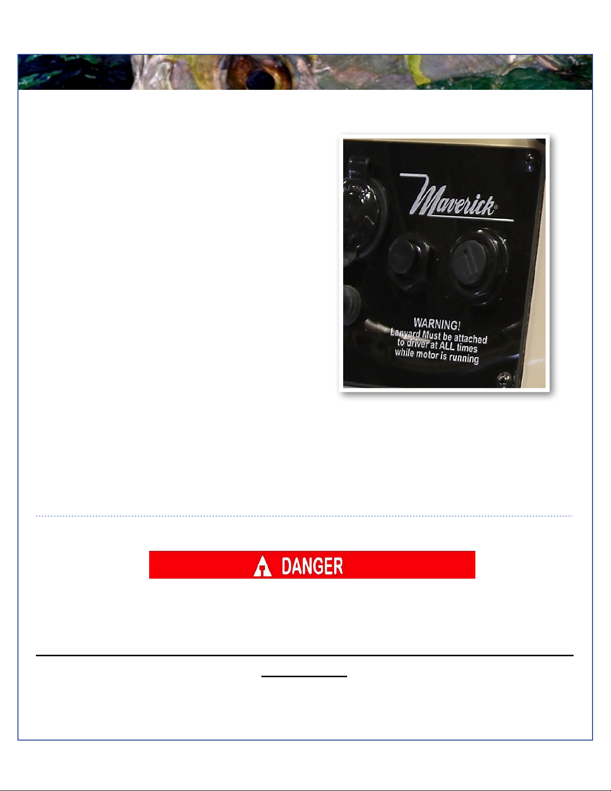
Ignition (above)
Engine Break-In Period
New engines require a period of break-in to allow the
surfaces of the moving parts to mate evenly. Different
engines require different break-in periods and methods.
For instructions on break in methods, refer to your
Yamaha Engine Owner’s Manual for the correct break-in
procedures and times for your model engines
Engine Stop Switch
If activated, the spring loaded engine stop switch will
automatically shut down the engine during emergency
situations to prevent uncontrolled or unattended
operation. Certain emergency conditions (e.g., turbulent
water, wakes, unanticipated movement) may impair a
person’s ability to operate the craft safely. The switch,
located on the helm, must have the safety lanyard
attached at its base. This activates the protective
shutdown circuitry.
Securely attach the other end of the lanyard to the
operator of the boat. If the operator moves, falls or is at
an unsafe distance from the steering wheel, tension on
the lanyard will pull it from the switch. When the lanyard is
removed, the engine stop switch is released and
automatic engine shutdown occurs.
Engine Stop Switch
An engine stop switch system that is not used or does not function properly can cause death or serious injury.
DO NOT operate the boat if the engine stop switch system does not function properly. Go to a Maverick Dealer to
have this resolved immediately
The lanyard should be securely attached to the boat operator at all times that the
engine is on.

Model year 2014! ! 5
Maverick Boat Company, Inc. • 3207 Industrial 29th St. • Fort Pierce,
Florida 34946 • (772)-465-0631 or (888)-shallow • Fax: (772) 489-2168
FUEL-WATER SEPARATOR & DRAIN
Fuel/Water Separator (above)
Fuel-Water Separator
Each boat is equipped with a fuel water separator to
ensure maximum performance and protect the outboard
engine from contaminated gasoline. The fuel separator
is a metal, cylindrical unit that can be accessed through
the aft bilge compartment.
The fuel separator can be checked by removing it from
the mounting bracket and dumping it into an approved
waste collection device. If there appears to be an
excessive amount of water, the filter component should
be changed. See your authorized Maverick dealer for
replacement parts.
Maintenance Note
In addition, the fuel separator should be changed as part of routine maintenance at 20, 50 and 100 hour checks.
Garboard Drain Plug
The garboard drain plug is the small metal plug located at
the lowest point on the hull, at the bottom of the transom
right above the keel. The drain has been designed so that
it can be loosened by hand while the hull is out of the
water for draining. This allows the plug to stay in contact
with the surrounding frame so you’ll never misplace or
lose it. You can completely remove the insert by pulling
back and continue turning in a counter clockwise motion.
It is manufactured with a rubber seal in place to ensure
you bilge is watertight. Always make sure before putting
the boat in the water that this plug is hand tightened
firmly. Excess water in the bilge may be an indication of a
problem with this plug or the automatic bilge pump. Refer
to page 10 of this Owner’s Manual for information on your
boats bilge system.

Model year 2014! ! 6
Maverick Boat Company, Inc. • 3207 Industrial 29th St. • Fort Pierce,
Florida 34946 • (772)-465-0631 or (888)-shallow • Fax: (772) 489-2168
SWITCH AND INSTRUMENTS
Gauges
The standard digital gauges include a Yamaha tachometer and a Yamaha speedometer. The tachometer has several built
in features including an engine temperature monitor, oil level monitor and engine trim indicator. The speedometer includes
a digital readout of the speed, an hour meter, trip meter and clock. For more information on the specifics of your Yamaha
gauges, see your Yamaha owner's manual.
Switch Panel
The dual activation switches are set in a standard grid.
These switches can be flipped either up or down to
control different accessories. The accessories located
directly above a switch are activated when the switch is
in the “Up” position and the accessories located directly
below the switch are activated when the switch is flipped
into the “Down” position. For example, in the “Up”
position the second switch to the left will turn on the
navigation lights, but if in the “Down” position it will turn
on the anchor light. The bilge switch is an on-demand
switch to run your bilge pump and is used as a backup in
case the float indicator in your bilge pump becomes
clogged. Switch Panel

Model year 2014! ! 7
Maverick Boat Company, Inc. • 3207 Industrial 29th St. • Fort Pierce,
Florida 34946 • (772)-465-0631 or (888)-shallow • Fax: (772) 489-2168
BOAT LAYOUT
DITTY BAG
You should have received a cloth ditty bag with your new Maverick. Inside the
ditty bag are the following items:
1 Large Livewell Standpipe
1 Small Livewell Standpipe
1 1-1/2”Livewell Pacifier Plug with Ring
2 ignition keys and Emergency Kill Cord
1 Engine Start Cord
1 1” Twist Tie Drain Plug
1 Gas Fill Key
3 Bungees for push pole holder
3 Push Pole Holders
Various Product Manuals
Mirage 17 HPX-V Boat Layout
Your Maverick is designed to create the maximum amount of storage capacity without affecting fishing ability. Livewells,
gasketed and guttered storage compartments and lockers are built to protect your gear from the elements.
Become familiar with the boat layout and features to take advantage of their special qualities. All Maverick boats are
designed by anglers, for anglers, to offer the best fishing features in the Bay Boat market. The Maverick superior layout
offers hands-free fishability with the most storage and casting room available.
Poling Tower
Fuel Fill
Forward Storage
Gunnel Rod
Holders
Livewell
Console

Model year 2014! ! 8
Maverick Boat Company, Inc. • 3207 Industrial 29th St. • Fort Pierce,
Florida 34946 • (772)-465-0631 or (888)-shallow • Fax: (772) 489-2168
BACKING PLATES
Backing Plates
The diagram below shows all the screw-retention backing plates originally placed in the deck of a 17 HPX-V during the
construction process.

Model year 2014! ! 9
Maverick Boat Company, Inc. • 3207 Industrial 29th St. • Fort Pierce,
Florida 34946 • (772)-465-0631 or (888)-shallow • Fax: (772) 489-2168
TROLLING MOTOR WIRING SYSTEM
Trolling Motor Wiring System
Your Maverick 17 HPX-V comes standard with a 24V trolling motor wiring system. A trolling motor mounting plate was built
into the bow of your Maverick during the manufacturing process. To attach a trolling motor, please go to your nearest
Maverick dealer. All trolling motors should be attached by drilling through the mounting plate with a 13/64” drill bit and 1/4”
tap and using 1/4” #20 machine screws. The plate is designed to accommodate the mounting patterns of all trolling motor
brands on the market currently. See below for optional trolling motor system with battery charger and wire routing.
Model year 2014! ! 10
Maverick Boat Company, Inc. • 3207 Industrial 29th St. • Fort Pierce,
Florida 34946 • (772)-465-0631 or (888)-shallow • Fax: (772) 489-2168
BALL VALVES AND LIVEWELL PUMP
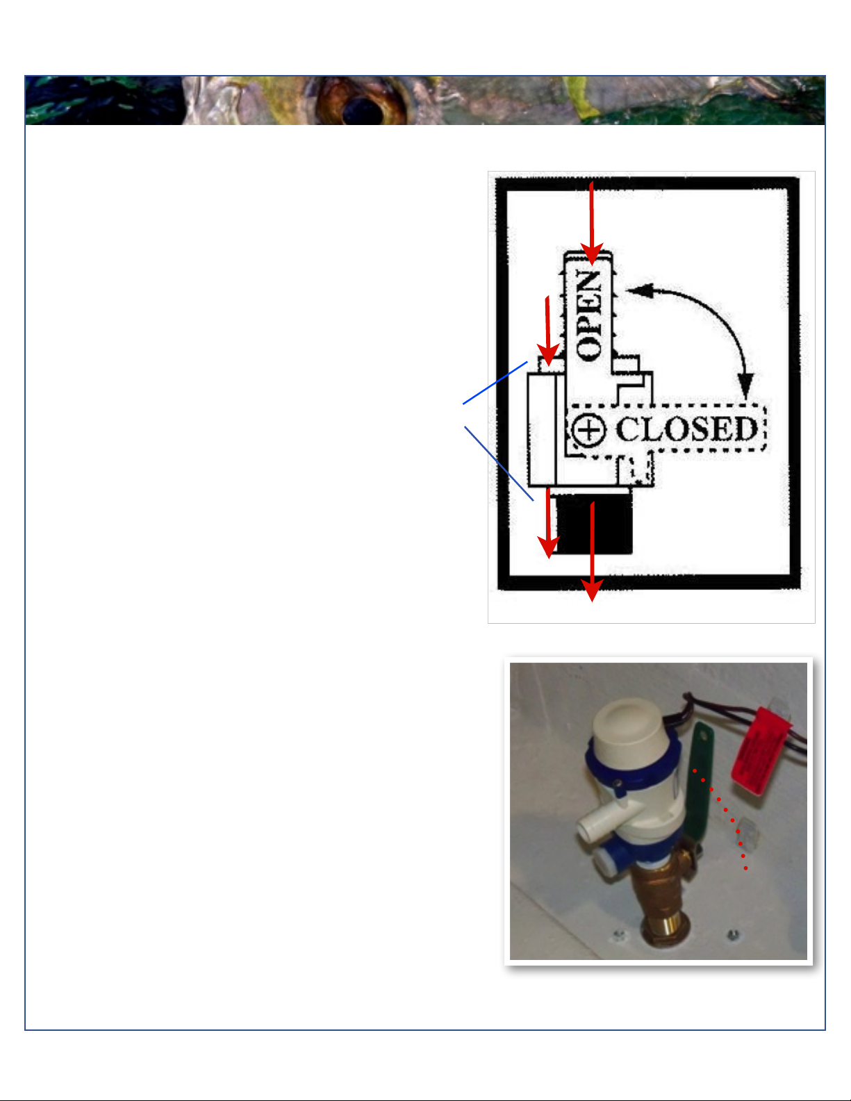
THE LIVEWELL PUMP
ASSEMBLY IN THE “OPEN
POSITION
Ball Valves
Ball valves can be used to serve several purposes. They
allow seawater to enter the boat, in the case of livewells,
and they also act as a safeguard to stop water from
entering in case of part failure, and function as an
emergency shutoff. To tell which position a ball valve is in,
open or closed, look at the valve and determine the
direction of flow. When the ball valve handle is in the
same position as the direction of flow, the valve is in the
“OPEN” position. When the ball valve handle appears to
cross the direction of flow, the valve is in the “CLOSED”
position.
Mirage Livewell Pump Assembly
The livewell pump assembly is composed of a scoop
strainer mounted to the bottom of the hull, a thru hull
fitting, ball valve assembly, and the pump. As you can
see, the ball valve assembly is in the “OPEN” position.
This is the correct position for the operation of the livewell
system.
Water Flow
CLOSED
Table of contents
Other Maverick Boat manuals


Popular Boat manuals by other brands


PURSUIT
PURSUIT OS 335 owner's manual

Boston Whaler
Boston Whaler CONQUEST 345 owner's manual

Jeanneau
Jeanneau SUN ODYSSEY 41 DS owner's manual

Meridian
Meridian 490 Pilothouse owner's manual

Advanced Elements
Advanced Elements AdvancedFrame Expedition AE1009 owner's manual

Robo Marine Indonesia
Robo Marine Indonesia GEOMAR user manual


