Masco MIS1-M1 User manual

Bedienungsanweisung
Manuel d’instruction
Operating instructions
Manuale istruzioni
Supporti per monitor
Monitor mounts
Supports pour moniteurs
Monitorhalterungen

DESCRIZIONE 3
INSTALLAZIONE 3
Installazione del supporto MID 3
Installazione del supporto MIS 3
SPECIFICHE TECNICHE 3
INDICE
ITALIANO Supporti per monitor
DESCRIPTION 4
INSTALLATION 4
Installation of MID support 4
Installation of MIS support 4
TECHNICAL SPECIFICATIONS 4
INDEX
ENGLISH Monitor mounts
DESCRIPTION 5
INSTALLATION 5
Installation du support MID 5
Installation du support MIS 5
SPÉCIFICATIONS TECHNIQUES 5
INDEX
FRANCAIS Supports pour moniteurs
BESCHREIBUNG 6
INSTALLATION 6
Halter-installation MID 6
Halter-installation MIS 6
TECHNISCHE DATEN 6
INHALTSVERZEICHNIS
DEUTSCH Monitorhalterungen

3
ITALIANO Supporti per monitor
DESCRIZIONE
Supporti per monitor realizzati completamente in
alluminio verniciato con polveri di epossipoliestere
che offrono ampie regolazioni ed aggiustamenti
per l’adattamento con diversi monitor. Sono
costituiti dall’unione di elementi modulari uguali
per tutte le imbragature, quali ad esempio gli
accessori per il montaggio. Il sistema di
imbragatura con tiranti ed angolari ricoperti di
gomma evita ogni danno al monitor.
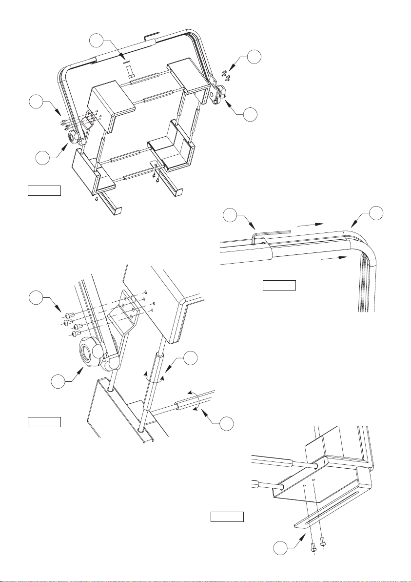
INSTALLAZIONE
Installazione del supporto MID
1. Inserire la vite M16 (1) e la rondella attraverso
il foro e serrarla al supporto a parete o al
supporto a soffitto.
2. Allentare i quattro grani con la chiave in
dotazione (2).
3. Allargare le due guide ad angolo (3) fino ad
ottenere la larghezza desiderata.
4. Serrare le otto viti laterali (4).
5. Inserire il monitor e agire sui tiranti in modo
omogeneo per il fissaggio (5).
6. Fissare i grani.
7. Agire sulle manopole laterali per regolare
l’inclinazione del monitor (6).
8. Per garantire una maggiore stabilità del
monitor fissare le staffette di sicurezza tramite
le viti in dotazione negli angolari inferiori (7).
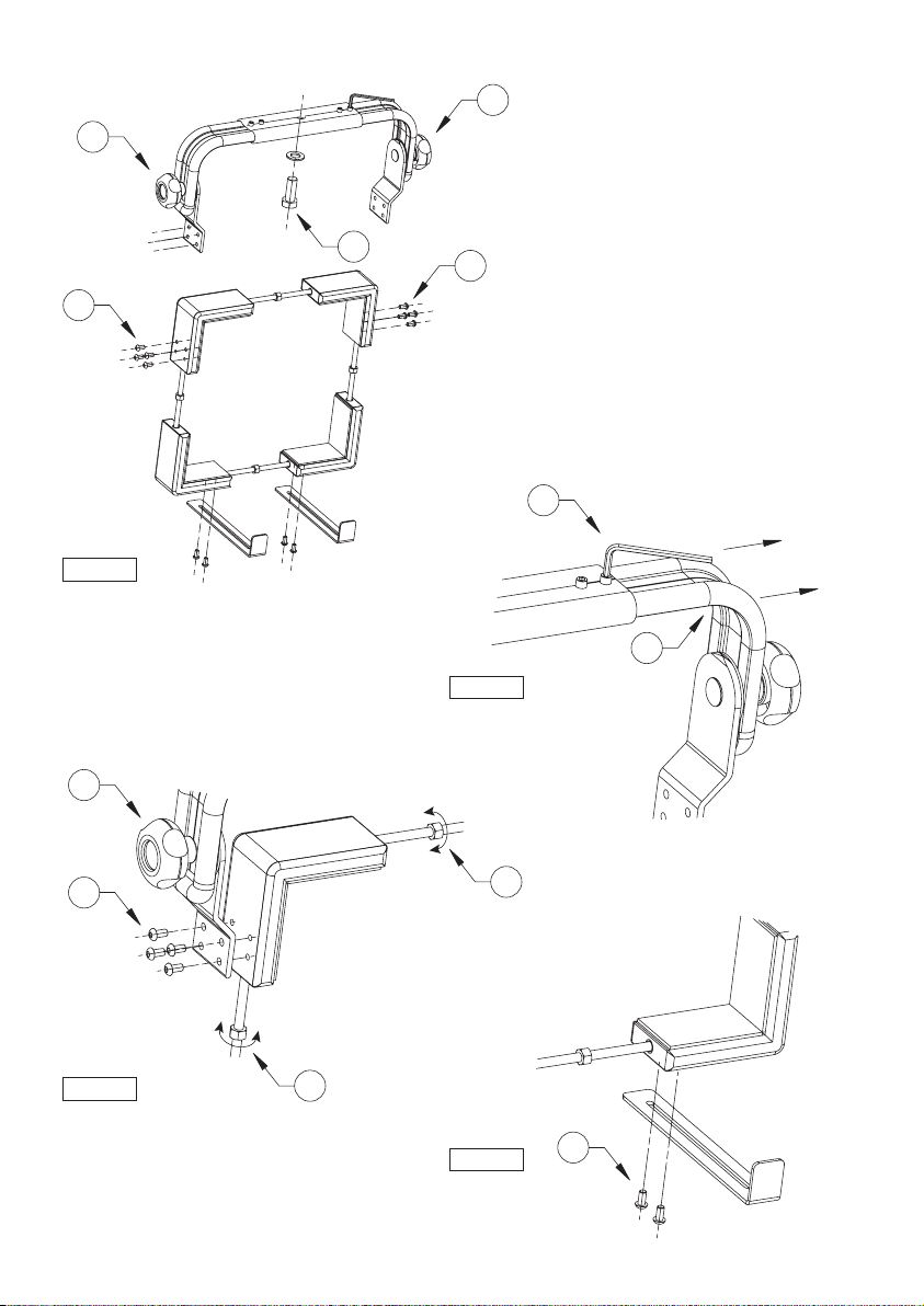
Installazione del supporto MIS
1. Inserire la vite M16 (8) e la rondella attraverso
il foro e serrarla al supporto a parete o al
supporto a soffitto.
2. Allentare i quattro grani con la chiave in
dotazione (9).
3. Allargare le due guide ad angolo (10) fino ad
ottenere la larghezza desiderata.
4. Serrare le otto viti laterali (11).
5. Inserire il monitor e agire sui tiranti in modo
omogeneo per il fissaggio (12).
6. Fissare i grani.
7. Agire sulle manopole laterali per regolare
l’inclinazione del monitor (13).
8. Per garantire una maggiore stabilità del
monitor fissare le staffette di sicurezza tramite
le viti in dotazione negli angolari inferiori (14).
SPECIFICHE TECNICHE
GENERALE
Realizzati in estrusione e tubo di alluminio
Verniciati a polveri di epossipoliestere colore grigio scuro
Protezione in gomma per monitor
MECCANICA
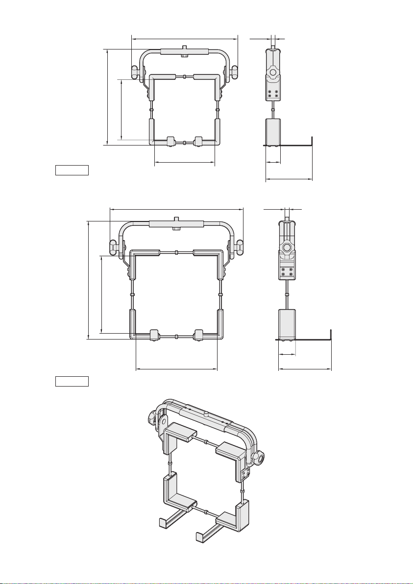
MIS1-M1
Dimensioni: min 210x210mm, max 320x350mm
Portata: 20kg
MIS2-M1
Dimensioni: min 255x210mm, max 370x350mm
Portata: 25kg
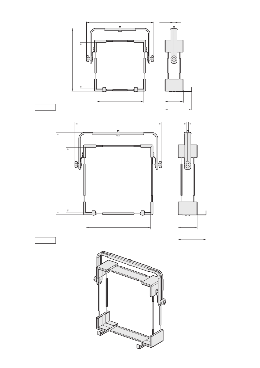
MID3-M1
Dimensioni: min 367x367mm, max 532x532mm
Portata: 35kg
MID4-M1
Dimensioni: min 510x510mm, max 675x675mm
Portata: 40kg
AMBIENTE
Interno

4
ENGLISH
Monitor mounts
DESCRIPTION
Monitor mounts entirely made of aluminium
painted with epoxypolyester powder offer a wide
range of adjustments so that they can be adapted
to monitors with the most various shape. They
consist of modular elements, which are the same
for all mounts, such as for example the mounting
accessories. The mounting system with tie-rods and
corner adaptors covered with rubber prevents the
monitor from being damaged.
INSTALLATION
Installation of MID support
1. Introduce the M16 screw (1) and the washer
through the hole and tighten it to the wall
support or the ceiling support.
2. Loosen the four grub screws by means of the
wrench supplied (2).
3. Widen the two angle guides (3) till obtaining
the width wished.
4. Tighten the eight lateral screws (4).
5. Introduce the monitor and operate homogeneously
on the tie rods in order to fix it (5).
6. Tighten the grub screws.
7. Operate on the lateral hand grips in order to
adjust the tilt of the monitor (6).
8. Fix the security brackets using the supplied
screws in the lower corners (7), in order to
guarantee a further monitor stability.
Installation of MIS support
1. Introduce the M16 screw (8) and the washer
through the hole and tighten it to the wall
support or the ceiling support.
2. Loosen the four grub screws by means of the
wrench supplied (9).
3. Widen the two angle guides (10) till obtaining
the width wished.
4. Tighten the eight lateral screws (11).
5. Introduce the monitor and operate homogeneously
on the tie rods in order to fix it (12).
6. Tighten the grub screws.
7. Operate on the lateral hand grips in order to
adjust the tilt of the monitor (13).
8. Fix the security brackets using the supplied
screws in the lower corners (14), in order to
guarantee a further monitor stability.
TECHNICAL SPECIFICATIONS
GENERAL
Made of extruded aluminium and aluminium tube
Painted with dark grey epoxypolyester powder
Rubber protection for monitor
MECHANICAL
MIS1-M1
Dimensions: min 210x210mm (8.3x8.3in), max 320x350mm
(12.6 x13.7in)
Load rating: 20kg (44lb)
MIS2-M1
Dimensions: min 255x 210mm (10x8.3in), max 370x350mm
(14.6x13.7in)
Load rating: 25kg (55lb)
MID3-M1
Dimensions: min 367x367mm (14.4x14.4in), max 532x532mm
(20.9x20.9in)
Load rating: 35kg (77lb)
MID4-M1
Dimensions: min 510x510mm (20x20in), max 675x675mm
(26.5x26.5in)
Load rating: 40kg (88lb)
ENVIRONMENT
Indoor

5
FRANCAIS Supports pour moniteurs
DESCRIPTION
Supports pour moniteurs fabriqués en aluminium
avec peinture époxy-polyester qui possèdent de
nombreuses possibilités de réglage, leur permettant
de s’adapter à différents types de moniteurs.
Constitués d’éléments modulaires compatibles,
leur montage mural ou plafond est simplifié. Le
système de blocage du moniteur avec les cornières
recouvertes de gomme prévient tout dommage au
moniteur.
INSTALLATION
Installation du support MID
1. Introduire la vis M16 (1) et la rondelle à
travers le trou et la fixer au support mural ou
au support plafond.
2. Desserrer les quatre vis sans tête au moyen de
la clé fournie (2).
3. Ecarter les deux guides à angle (3) jusqu’à
obtenir la largeur désirée.
4. Serrer les huit vis latérales (4).
5. Introduire le moniteur et agir de façon
homogène sur les tirants pour la fixation (5).
6. Fixer les vis sans tête.
7. Agir sur les poignées latérales pour régler
l’inclinaison du moniteur (6).
8. Fixer les étriers de sécurité en utilisant les vis
fournies présentes dans les angles inférieurs
(7), à fin de garantir une stabilité majeure du
moniteur.
Installation du support MIS
1. Introduire la vis M16 (8) et la rondelle à
travers le trou et la fixer au support mural ou
au support plafond.
2. Desserrer les quatre vis sans tête au moyen de
la clé fournie (9).
3. Ecarter les deux guides à angle (10) jusqu’à
obtenir la largeur désirée.
4. Serrer les huit vis latérales (11).
5. Introduire le moniteur et agir de façon
homogène sur les tirants pour la fixation (12).
6. Fixer les vis sans tête.
7. Agir sur les poignées latérales pour régler
l’inclinaison du moniteur (13).
8. Fixer les étriers de sécurité en utilisant les vis
fournies présentes dans les angles inférieurs
(14), à fin de garantir une stabilité majeure du
moniteur.
SPÉCIFICATIONS TECHNIQUES
GÉNÉRALITÉS
Réalisé en profilé d’aluminium et tube d’aluminium
Verni avec peinture époxypolyester, couleur noir gris
Protections en caoutchouc pour moniteurs
MÉCANIQUE
MIS1-M1
Dimensions: min 210x210mm, max 320x350mm
Charge utile: 20kg
MIS2-M1
Dimensions: min 255x 210mm, max 370x350mm
Charge utile: 25kg
MID3-M1
Dimensions: min 367x367mm, max 532x532mm
Charge utile: 35kg
MID4-M1
Dimensions: min 510x510mm, max 675x675mm
Charge utile: 40kg
ENVIRONNEMENT
Intérieur

6
DEUTSCH
Monitorhalterungen
TECHNISCHE DATEN
ALLGEMEINES
Hergestellt aus Alu-Strangpreßteilen und -rohren
Schwarzes Grau-Farbe Epoxydpulverbeschichtung
Gummischutz für Monitor
MECHANIK
MIS1-M1
Abmessungen: min 210x210mm, max 320x350mm
Tragfähigkeit: 20kg
MIS2-M1
Dimensioni: min 255x 210mm, max 370x350mm
Tragfähigkeit: 25kg
MID3-M1
Abmessungen: min 367x367mm, max 532x532mm
Tragfähigkeit: 35kg
MID4-M1
Abmessungen: min 510x510mm, max 675x675mm
Tragfähigkeit: 40kg
UMGEBUNG
Für innere Installationen
BESCHREIBUNG
Monitorhalterungen bestehen ganz aus
Epoxypolyester-lackiertem Aluminium und sind
weitgehend einstell- und anpassbar, um sie für
Monitore der unterschiedlichsten Formen benutzen
zu können. Alle Halterungen, beispielsweise
auch die Zubehörteile für die Montage, werden
aus gleichen maßeinheitlichen Elementen
zusammengesetzt. Die Gummiverkleidungen an
Halterungen und Eckteilen sorgen dafür, daß
Beschädigungen am Monitor verhindert werden.
INSTALLATION
Halter-installation MID
1. Schraube M16 (1) und Scheibe durch die
Bohrung einlegen und sie an dem Wand-
Halter oder an dem Decke-Halter anziehen.
2. Mit dem Ausstattungsschlüßel die vier Stifte
losmachen (2).
3. Die zwei Eckenführungen sind bis zur
gewünschten Weite auszuweiten (3).
4. Die acht seitlichen Schrauben anziehen (4).
5. Den Monitor einlegen und die dazugehörenden
Zugstäben für die entsprechende Befestigung
(5) gleichmäßig betätigen.
6. Danach die Stiften befestigen.
7. Durch die seitlichen Drehknöpfe die Neigung
des Monitors einstellen (6).
8. Die Sicherheitsbügel mit den mitgelieferten
Schrauben in den Unterwinkeln befestigen (7),
um eine höhere Monitorstabilität zu versichern.
Halter-installation MIS
1. Schraube M16 (8) und Scheibe durch die
Bohrung einlegen und sie an dem Wand-
Halter oder an dem Decke-Halter anziehen.
2. Mit dem Ausstattungsschlüßel die vier Stifte
losmachen (9).
3. Die zwei Eckenführungen sind bis zur
gewünschten Weite auszuweiten (10).
4. Die acht seitlichen Schrauben anziehen (11).
5. Den Monitor einlegen und die dazugehörenden
Zugstäben für die entsprechende Befestigung
(12) gleichmäßig betätigen.
6. Danach die Stiften befestigen.
7. Durch die seitlichen Drehknöpfe die Neigung
des Monitors einstellen (13).
8. Die Sicherheitsbügel mit den mitgelieferten
Schrauben in den Unterwinkeln befestigen
(14), um eine höhere Monitorstabilität zu
versichern.
7
23
4
5
5
6
4
6
4
6
1
Fig. 1
Fig. 2
Fig. 3
7
Fig. 4
8
9
10
11 12
12
13
11
13
11
13
8
Fig. 5
Fig. 6
14
Fig. 7
Fig. 8
9
570 - 720 M16
175
140 - 260
530 - 680
370 - 520
370 - 520
710 - 860
670 - 820
510 - 660
175
140 - 260
510 - 660
M16
MID3-M1
MID4-M1
10
210 - 320
410 - 520
210 - 350
367 - 507
65
85 - 205
M16
455 - 570
255 - 370
210 - 350
367 - 507
65
85 - 205
M16
MIS1-M1
MIS2-M1
This manual suits for next models
3
Table of contents
Languages:
Popular Rack & Stand manuals by other brands

Salamander
Salamander Acadia AC/W/L400/WH Assembly instructions

Fohhn
Fohhn VAT-09 Mounting instruction

ricoo
ricoo FS0522 quick start guide

AMSOIL
AMSOIL BMK-22 Installation and service instructions

Kargo Master
Kargo Master 48220 installation guide

Milestone AV Technologies
Milestone AV Technologies SIMPLICITY SLF2 installation instructions


