Mannesmann Rexroth Brueninghaus Hydromatik A2F/6.1... Setup guide

R
MANNESMANN
REXROTH
Brueninghaus Hydromatik
RDE 91001-01-R
07.96
Reparaturanleitung
Repair Instructions
A2F
Baureihe/Series 6.1
RETURN TO TABLE OF CONTENTS

2 Brueninghaus Hydromatik
RDE 91001-01-R/07.96
Reparaturanleitung A2F/6.1
Repair Instructions A2F/6.1
NOTICE
Specifications, descriptions and illustrative material
shown herein were as accurate as known at the time
this publication was approved for printing.
BRUENINGHAUS HYDROMATIK reserves the right to
discontinue models or options at any time or to change
speci-fications, materials, or design without notice and
with-out incurring obligation.
Optional equipment and accessories may add cost to
the basic unit, and some options are available only in
combination with certain models or other options.
For the available combinations refer to the relevant data
sheet for the basic unit and the desired option.
Adjustment and tests have to be carried out on the test
bench under operating temperatures.
Protection of personnel and property has to be guar-
anteed by appropriate measures.
Expert knowledge, the precondition of any service work,
can be obtained in our training courses.
CONTENTS
A2F
Sectional view
General repair instructions
Seal kits and sub-assemblies
Sealing of the drive shaft
Sealing of the cover plate
Removal the rotary group
Examination notes
Installing rotary group
Tightening torques
Safety regulations
HINWEIS
Bezeichnungen, Beschreibungen und Darstellungen
entsprechen dem Informationsstand zum Zeitpunkt der
Drucklegung dieser Unterlage.
Änderungen können den Service am Produkt beein-
flussen, Verpflichtungen entstehen uns daraus nicht.
Methoden und Vorrichtungen sind Empfehlungen, für
deren Resultat wir keine Haftung übernehmen können.
BRUENINGHAUS HYDROMATIK- Baugruppen, mit
Angabe der Fabrik-Nr. bestellt, sind die Basis guter
Reparaturen.
Einstell- und Prüfarbeiten sind bei Betriebstemperatur
auf dem Teststand vorzunehmen.
Schutz von Personen und Eigentum ist durch Vor-
kehrungen sicherzustellen.
Sachkenntnis, die Voraussetzung für jede Service-
arbeit, vermitteln wir in unseren Schulungskursen.
INHALT Seite/
Page
A2F
Schnittbild 3
AllgemeineReparaturhinweise 4
Dichtsätze und Baugruppen 5
Triebwelle abdichten 6-7
Anschlußplatte abdichten 8-9
Triebwerk ausbauen 10
Überprüfungshinweise 11-12
Triebwerk ausbauen 13-15
Anziehdrehmomente 16
Sicherheitsbestimmungen 17-18
Inhalt / Hinweis
Contents / Notice

RDE 91001-01-R/07.96
Brueninghaus Hydromatik 3
Reparaturanleitung A2F/6.1
Repair Instructions A2F/6.1
Schnittbild
Sectional view
Meßpunkte:
Siehe Serviceinfo
Measuring points:
See service information

4 Brueninghaus Hydromatik
RDE 91001-01-R/07.96
Reparaturanleitung A2F/6.1
Repair Instructions A2F/6.1
Achtung!
Nachfolgende Hinweise bei allen Reparaturarbeiten
an Hydraulikaggregaten beachten!
Attention!
Observe the following notices when carrying out repair
work at hydraulic aggregates!
Alle Öffnungen der Hydraulikaggregate verschließen.
Close all ports of the hydraulic aggregates.
Alle Dichtungen erneuern.
Nur original HYDROMATIK - Ersatzteile verwenden!
Replace all seals.
Use only original HYDROMATIK spare parts!
Alle Dicht- und Gleitflächen auf Verschleiß prüfen.
Achtung: Nacharbeiten an Dichtflächen z.B. durch
Schleifpapier kann die Oberfläche beschädigen.
Check all seal and sliding surfaces for wear.
Attention: Rework of sealing area f. ex. with abrasive
paper can damage surface.
Hydraulikaggregate vor Inbetriebnahme mit
Hydrauliköl befüllen.
Fill up hydraulic aggregates with hydraulic oil
before start- up.
AllgemeineReparaturhinweise
General repair instructions

RDE 91001-01-R/07.96
Brueninghaus Hydromatik 5
Reparaturanleitung A2F/6.1
Repair Instructions A2F/6.1
1 Äußerer Dichtsatz.
External seal kit.
2 Triebwerk, mechanischer Teil; mit Dichtsatz,
muß abgestimmt werden auf Maß "A".
Rotary group, mechanical part; with seal kit,
has to be adjusted to dimension "A".
3 Triebwerk, hydraulischer Teil; mit Dichtsatz,
Abstimmung hydraulischer Teil Pos. "D".
Rotary group, hydraulic part; with seal kit,
Adjustment of the hydraulic part Pos. "D".
4 Triebwerk komplett; mit Dichtsatz, fertig vorabgestimmt.
Abstimmung hydraulischer Teil Pos. "D".
Complete rotary group, with seal kit, pre-adjusted.
Adjustment of the hydraulic part Pos. "D".
Dichtsätze und Baugruppen
Seal kits and sub-assemblies

6 Brueninghaus Hydromatik
RDE 91001-01-R/07.96
Reparaturanleitung A2F/6.1
Repair Instructions A2F/6.1
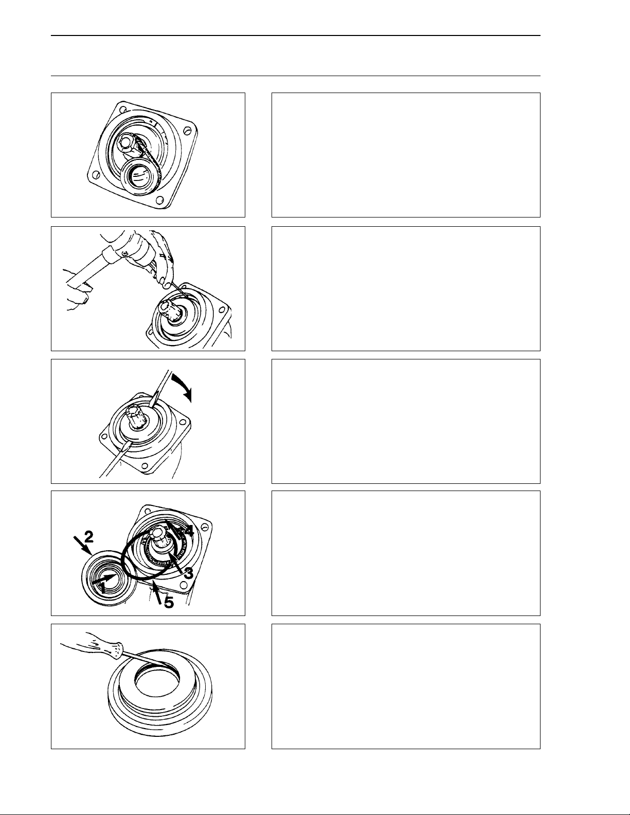
5 Bei nicht verzahnten Triebwellen: Paßfeder ab-
nehmen. Triebwelle abkleben,
Remove protective cover. If keyed shaft,remove
key.
6 Sicherungsring lösen, danach ausbauen.
Free circlip and remove.
7 Verschlußring abdrücken.
Prise off front cover
8 Sichtkontrolle
Wellendichtring (1), Verschlußring (2), Trieb-
welle (3), Gehäuse (4), O-Ring (5).
Visual check
Shaft seal (1), cover (2), drive shaft (3),
housing (4), O-ring (5).
9 Wellendichtring demontieren.
Remove old shaft seal.
Triebwelle abdichten
Sealing of the drive shaft

RDE 91001-01-R/07.96
Brueninghaus Hydromatik 7
Reparaturanleitung A2F/6.1
Repair Instructions A2F/6.1
10 Neuen Wellendichtring lagerichtig mit passender
Büchse einpressen.
Press in the shaft seal ring to the correCt position
with a suitable sleeve.
11 Bei tiefer Laufrille beiliegende Scheibe vor den
Wellendichtring einlegen.
If the shaft is deeply grooved, insert shim
behind seal.
12 Neuen O-Ring einlegen, auf bündiges Anliegen
achten. O-Ring sowie Dicht- und Staublippe des
wellendichtringes einfetten.
Fit new O-ring, ensure it is a snug rit. Grease
O-ring and lips or shaft seal.
13 Sicherungsring mit Durchschlag einsprengen.
Fit circlip using a punch.
14 Sitzkontrolle des Sicherungsringes in der Nut.
Check that circlip is well seated.
Triebwelle abdichten
Sealing of the drive shaft

8 Brueninghaus Hydromatik
RDE 91001-01-R/07.96
Reparaturanleitung A2F/6.1
Repair Instructions A2F/6.1
15 Lage der Anschlußplatte zum Gehäuse kennzeichnen
(Pfeil), Befestigungsschrauben lösen.
Mark position of cover plate (arrowed). Remove screws.
16 Anschlußplatte um Verdrillstift schwenken (1)
und abheben (2).
Swivel port plate on locating pin and lift off.
17 Auf Montagestellung des Verdrillstiftes achten (Pfeile).
Note position of locating pin. (arrow).
18 Pumpe, Drehrichtung rechts. (Blick auf sphärische Fläche.)
Pump, clockwise rotation. (viewed on spherical surface.)
19 Pumpe, Drehrichtung links. (Blick auf sphärische Fläche.)
Pump, anti-clockwise rotation. (viewed on spherical
surface.)
Anschlußplatte abdichten
Sealing of the cover plate

RDE 91001-01-R/07.96
Brueninghaus Hydromatik 9
Reparaturanleitung A2F/6.1
Repair Instructions A2F/6.1
20 Motor, beide Drehrichtungen. (Blick auf sphärische Fläche.)
Motor, bi-directional. (Viewed on spherical surface.)
21 Sichtkontrolle
O-Ring (1), Einstich (2), Platte (3).
Visual check
O-ring (1), Groove (2), Plate (3).
22 Neuen O-Ring einlegen, zuvor leicht einfetten.
Lightly grease and fit O-ring.
23 Anschlußplatte aufsetzen, auf Kennzeichnung
(Bild 15) und Lage des Verdrillstiftes achten (18-20).
Assemble port plate to original mark (15), noting
position of port plate (18-20).
See notes fitting control plate.
24 Befestigungsschrauben mit Drehmomentenschlüssel
anziehen. Momente Seite 16.
Tighten screws using torque wrench. See page 16
for setting.
Anschlußplatte abdichten
Sealing of the cover plate

10 Brueninghaus Hydromatik
RDE 91001-01-R/07.96
Reparaturanleitung A2F/6.1
Repair Instructions A2F/6.1
25 Demontage der Anschlußplatte (Seite 8). Steuerplatte
drehend abheben.
Remove cover plate (page 8). Rotate control
plate to remove.
26 Demontage des Verschlußringes (Seite 6, 7).
Remove front cover (page 6, 7).
27 Paßscheibe(n) entnehmen.
Remove shim(s).
28 Triebwerk mit Vorrichtung ausbauen. Vorrichtung Bild 54.
Remove rotary group with extractor. (See fig.54).
29 Rückzugplatte demontieren, Schrauben sind eingeklebt.
Hinweis: Schrauben erwärmen.
Remove retaining plate. The screws are held by Loctite.
Note: Warm up screws.
Triebwerk ausbauen
Removal the rotary group