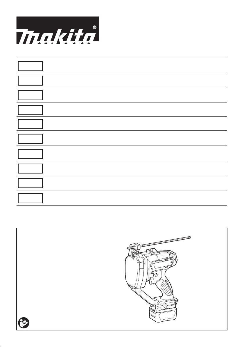
Makita SC103D User manual

SC103D
EN Cordless Threaded Rod
Cutter INSTRUCTION MANUAL 7
FR Coupe Tige Filetée Sans Fil MANUEL D’INSTRUCTIONS 13
DE Akku-
Gewindestangenschneider BETRIEBSANLEITUNG 20
IT Tagliabarre lettate a batteria ISTRUZIONI PER L’USO 28
NL Accudraadstangsnijder GEBRUIKSAANWIJZING 35
ES Cortadora Inalámbrica de
Varilla
MANUAL DE
INSTRUCCIONES 42
PT Cortadora de Barra Roscada
a Bateria MANUAL DE INSTRUÇÕES 49
DA Akku gevindstangsklipper BRUGSANVISNING 56
EL Φορητός κόφτης
σπειροτομημένων ράβδων ΕΓΧΕΙΡΙΔΙΟ ΟΔΗΓΙΩΝ 62
TR Akülü Dişli Mil Kesme
Makinası KULLANMA KILAVUZU 70

13
14
5
7
12
9
11
10
6
15
8
1
2
3
4
4
Fig.1
1
2
3
Fig.2
1
2
Fig.3
1
Fig.4
1
3
2
Fig.5
2

1
23
4
Fig.6
1
Fig.7
1
2
Fig.8
2
1
3
Fig.9
1 2
Fig.10
1
Fig.11
Fig.12
1
Fig.13
3

1
2
23
3
Fig.14
1
Fig.15
1
2
3
4
5
6
1
2
Fig.16
1
2
3
4
Fig.17
1
Fig.18
4

1
2
Fig.19
1 2
Fig.20
1 2
Fig.21
1
2
34
Fig.22
12
Fig.23
1
2
3
Fig.24
5

1
Fig.25
6

7ENGLISH
ENGLISH (Original instructions)
SPECIFICATIONS
Model: SC103D
Cutting capacities Mild steel
W3/8, W5/16, W1/4, 3/8-16UNC, 5/16-18UNC, 1/4-20UNC, M10, M8, M6
Stainless steel W3/8, 5/16-18UNC, M8, M6
Overall length 180 mm
Rated voltage D.C. 10.8 V - 12 V max
Net weight 2.7 - 2.8 kg
•
Due to our continuing program of research and development, the specications herein are subject to change without notice.
• Specications may differ from country to country.
• The weight may differ depending on the attachment(s), including the battery cartridge. The lightest and heavi-
est combination, according to EPTA-Procedure 01/2014, are shown in the table.
Applicable battery cartridge and charger
Battery cartridge BL1015 / BL1016 / BL1020B / BL1021B / BL1040B / BL1041B
Charger DC10SA / DC10SB / DC10WC / DC10WD / DC18RE
•
Some of the battery cartridges and chargers listed above may not be available depending on your region of residence.
WARNING: Only use the battery cartridges and chargers listed above. Use of any other battery cartridges
and chargers may cause injury and/or re.
Symbols
The followings show the symbols used for the equipment.
Be sure that you understand their meaning before use.
Read instruction manual.
Wear safety glasses.
Do not touch the cutting dies during
operation.
Pay attention to a cut threaded rod.
Do not close your face to the tool during
operation.
Ni-MH
Li-ion
Only for EU countries
Do not dispose of electric equipment or
battery pack together with household waste
material!
In observance of the European Directives,
on Waste Electric and Electronic Equipment
and Batteries and Accumulators and Waste
Batteries and Accumulators and their imple-
mentation in accordance with national laws,
electric equipment and batteries and battery
pack(s) that have reached the end of their life
must be collected separately and returned to an
environmentally compatible recycling facility.
Intended use
The tool is intended for cutting threaded rods.
Noise
The typical A-weighted noise level determined accord-
ing to EN62841-2-8:
Sound pressure level (LpA) : 70 dB(A)
Uncertainty (K) : 3 dB(A)
The noise level under working may exceed 80 dB (A).
NOTE:
The declared noise emission value(s) has been
measured in accordance with a standard test method
and may be used for comparing one tool with another.
NOTE:
The declared noise emission value(s) may
also be used in a preliminary assessment of exposure.
WARNING: Wear ear protection.
WARNING:
The noise emission during actual
use of the power tool can differ from the declared
value(s) depending on the ways in which the tool is
used especially what kind of workpiece is processed.
WARNING:
Be sure to identify safety measures
to protect the operator that are based on an estima-
tion of exposure in the actual conditions of use (tak-
ing account of all parts of the operating cycle such
as the times when the tool is switched off and when
it is running idle in addition to the trigger time).
Vibration
The vibration total value (tri-axial vector sum) deter-
mined according to EN62841-2-8:
Work mode: cutting threaded stainless steel rod (rod size W3/8)
Vibration emission (ah) : 2.5 m/s2or less
Uncertainty (K) : 1.5 m/s2

8ENGLISH
NOTE: The declared vibration total value(s) has been
measured in accordance with a standard test method
and may be used for comparing one tool with another.
NOTE: The declared vibration total value(s) may also
be used in a preliminary assessment of exposure.
WARNING:
The vibration emission during actual
use of the power tool can differ from the declared val-
ue(s) depending on the ways in which the tool is used
especially what kind of workpiece is processed.
WARNING:
Be sure to identify safety measures
to protect the operator that are based on an estima-
tion of exposure in the actual conditions of use (tak-
ing account of all parts of the operating cycle such
as the times when the tool is switched off and when
it is running idle in addition to the trigger time).
EC Declaration of Conformity
For European countries only
The EC declaration of conformity is included as Annex A
to this instruction manual.
SAFETY WARNINGS
General power tool safety warnings
WARNING:
Read all safety warnings, instruc-
tions, illustrations and specications provided with this
power tool. Failure to follow all instructions listed below
may result in electric shock, re and/or serious injury.
Save all warnings and instruc-
tions for future reference.
The term "power tool" in the warnings refers to your
mains-operated (corded) power tool or battery-operated
(cordless) power tool.
Cordless threaded rod cutter safety
warnings
1. Hold the tool rmly.
2. Secure the workpiece rmly.
3. Keep your face and hands away from moving
parts. During cutting, the fraction of the threaded
rod may y off.
4. Always wear gloves when handling threaded
rods. Edges and chips of the workpiece are sharp.
5. Do not put the tool on the chips of the work-
piece. Otherwise it can cause damage and
trouble on the tool.
6. Always be sure you have a rm footing. Be
sure no one is below when using the tool in
high locations.
7. Do not touch the cutting edge or the workpiece
immediately after operation; they may be
extremely hot and could burn your skin.
8. Avoid cutting electrical wires. It can cause
serious accident by electric shock.
9. Always hold the threaded rod during and after
cutting to prevent the cut threaded rod from
falling off. A cut threaded rod may cause serious
personal injury if fallen off from a high location.
10.
Keep a safe distance between your body and the
moving parts. Do not operate the tool if the work-
ing area is too narrow to keep a safe distance.
11. Never leave the tool on a high location or a
potentially unstable surface.
SAVE THESE INSTRUCTIONS.
WARNING:
DO NOT let comfort or familiarity
with product (gained from repeated use) replace strict
adherence to safety rules for the subject product.
MISUSE or failure to follow the safety rules stated in this
instruction manual may cause serious personal injury.
Important safety instructions for
battery cartridge
1.
Before using battery cartridge, read all instruc-
tions and cautionary markings on (1) battery
charger, (2) battery, and (3) product using battery.
2. Do not disassemble battery cartridge.
3. If operating time has become excessively
shorter, stop operating immediately. It may
result in a risk of overheating, possible burns
and even an explosion.
4.
If electrolyte gets into your eyes, rinse them out
with clear water and seek medical attention right
away. It may result in loss of your eyesight.
5. Do not short the battery cartridge:
(1) Do not touch the terminals with any con-
ductive material.
(2) Avoid storing battery cartridge in a con-
tainer with other metal objects such as
nails, coins, etc.
(3) Do not expose battery cartridge to water
or rain.
A battery short can cause a large current ow,
overheating, possible burns and even a breakdown.
6. Do not store the tool and battery cartridge in
locations where the temperature may reach or
exceed 50 °C (122 °F).
7. Do not incinerate the battery cartridge even if
it is severely damaged or is completely worn
out. The battery cartridge can explode in a re.
8. Be careful not to drop or strike battery.
9. Do not use a damaged battery.
10.
The contained lithium-ion batteries are subject to
the Dangerous Goods Legislation requirements.
For commercial transports e.g. by third parties,
forwarding agents, special requirement on pack-
aging and labeling must be observed.
For preparation of the item being shipped, consulting an
expert for hazardous material is required. Please also
observe possibly more detailed national regulations.
Tape or mask off open contacts and pack up the battery in
such a manner that it cannot move around in the packaging.
11. When disposing the battery cartridge, remove
it from the tool and dispose of it in a safe
place. Follow your local regulations relating to
disposal of battery.

9ENGLISH
12. Use the batteries only with the products
specied by Makita. Installing the batteries to
non-compliant products may result in a re, exces-
sive heat, explosion, or leak of electrolyte.
13. If the tool is not used for a long period of time,
the battery must be removed from the tool.
SAVE THESE INSTRUCTIONS.
CAUTION:
Only use genuine Makita batteries.
Use of non-genuine Makita batteries, or batteries that
have been altered, may result in the battery bursting
causing res, personal injury and damage. It will also
void the Makita warranty for the Makita tool and charger.
Tips for maintaining maximum
battery life
1.
Charge the battery cartridge before completely dis-
charged. Always stop tool operation and charge the
battery cartridge when you notice less tool power.
2.
Never recharge a fully charged battery cartridge.
Overcharging shortens the battery service life.
3.
Charge the battery cartridge with room tempera-
ture at 10 °C - 40 °C (50 °F - 104 °F). Let a hot
battery cartridge cool down before charging it.
PARTS DESCRIPTION
► Fig.1
1Stationary mount 2Movable mount 3Cutting die 4Bolt
5Hook 6Shoulder strap base
(for optional accessory)
7Hex Wrench 8Lamp (inside)
9Front face 10 Switch trigger 11 Reversing switch lever 12 Rod guide
13 Guide scale 14 Clamping screw 15 Cover - -
FUNCTIONAL DESCRIPTION
CAUTION: Always be sure that the tool is
switched off and the battery cartridge is removed
before adjusting or checking function on the tool.
Installing or removing battery cartridge
CAUTION: Always switch off the tool before
installing or removing of the battery cartridge.
CAUTION: Hold the tool and the battery car-
tridge rmly when installing or removing battery
cartridge. Failure to hold the tool and the battery
cartridge rmly may cause them to slip off your hands
and result in damage to the tool and battery cartridge
and a personal injury.
► Fig.2: 1. Red indicator 2. Button 3. Battery cartridge
To remove the battery cartridge, slide it from the tool
while sliding the button on the front of the cartridge.
To install the battery cartridge, align the tongue on the
battery cartridge with the groove in the housing and slip
it into place. Insert it all the way until it locks in place
with a little click. If you can see the red indicator on the
upper side of the button, it is not locked completely.
CAUTION: Always install the battery cartridge
fully until the red indicator cannot be seen. If not,
it may accidentally fall out of the tool, causing injury to
you or someone around you.
CAUTION: Do not install the battery cartridge
forcibly. If the cartridge does not slide in easily, it is
not being inserted correctly.
Tool / battery protection system
The tool is equipped with a tool/battery protection sys-
tem. This system automatically cuts off power to the
motor to extend tool and battery life. The tool will auto-
matically stop during operation if the tool or battery is
placed under one of the following conditions.
Overload protection
When the tool is operated in a manner that causes it to
draw an abnormally high current, the tool automatically
stops without any indication. In this situation, turn the
tool off and stop the application that caused the tool to
become overloaded. Then turn the tool on to restart.
NOTE: Overload protection activates when you try to
cut the following kinds of threaded rods.
— A threaded rod which is larger than the cutting
die size.
— A threaded rod which is harder than the cutting
capacity of the cutting dies.
Overheat protection
When the tool is overheated, the tool automatically
stops and the LED light will blink. Let the tool cool down
before turning the tool on again.
Overdischarge protection
When the battery capacity becomes low, the tool stops
automatically. If the product does not operate even
when the switches are operated, remove the batteries
from the tool and charge the batteries.

10 ENGLISH
Indicating the remaining battery capacity
Only for battery cartridges with the indicator
► Fig.3: 1. Indicator lamps 2. Check button
Press the check button on the battery cartridge to indi-
cate the remaining battery capacity. The indicator lamps
light up for a few seconds.
Indicator lamps Remaining
capacity
Lighted Off
75% to 100%
50% to 75%
25% to 50%
0% to 25%
NOTE: Depending on the conditions of use and the
ambient temperature, the indication may differ slightly
from the actual capacity.
Switch action
CAUTION: Before installing the battery car-
tridge into the tool, always check to see that the
switch trigger actuates properly and returns to
the "OFF" position when released.
To start the cutting operation, continue to pull the switch
trigger. The cutting die on the movable mount will
overlap with the die on the stationary mount and then
returns. If you release the switch trigger before complet-
ing the cut, the cutting dies will stop.
► Fig.4: 1. Switch trigger
► Fig.5: 1. Stationary mount 2. Cutting die 3. Movable
mount
NOTICE: Do not operate the tool at no-load
unnecessarily.
Auto-stop function
When you continue to pull the switch trigger, the jaw of
the dies once closes and returns to fully opened posi-
tion then stops. Release the trigger and pull it again to
begin the next cutting sequence.
Reversing switch lever
WARNING: When not operating the tool,
always set the reversing switch lever to the lock
position.
CAUTION: Always make sure the position of
the reversing switch lever before operating.
NOTICE: Do not move the reversing switch lever
when the switch trigger is being pulled. This may
cause a damage to the tool.
To start the cutting operation, set the reversing switch
lever to cutting position.
To reverse the cutting sequence, set the reversing
switch lever to the reversing position. When you con-
tinue to pull the switch trigger, the jaw of the cutting die
opens and stops at fully opened position.
To lock the switch trigger, set the reversing switch lever to the
lock position. The switch trigger cannot be pulled in this position.
► Fig.6: 1. Reversing switch lever 2. Cutting position
3. Lock position 4. Reversing position
NOTICE:
When the reversing switch lever is in the
reversing position, run the tool only as needed. To
prevent the damage to the tool, the tool will automatically
stops when it is run in the reversing position continuously.
NOTE:
After cutting, if you release the switch trigger while
the jaw of the cutting die is opening and then set the revers-
ing switch lever to the reversing position, the jaw will once
close and then open when you pull the switch trigger again.
LED light
CAUTION: Do not look in the light or see the
source of light directly.
Pull the switch trigger to light up the lamp. The lamp
keeps on lighting while the switch trigger is being pulled.
The lamp goes out approximately 15 seconds after
releasing the switch trigger.
► Fig.7: 1. Lamp (inside)
NOTE: Use a dry cloth to wipe the dirt off the lens of
the lamp. Be careful not to scratch the lens of lamp, or
it may lower the illumination.
NOTE: When the tool is overheated, the lamp will
blink. Let the tool cool down in this case.
Guide scale
Use the guide scale if you wish to cut threaded rods in
the same length. Insert the guide scale into the hole as
shown in the gure.
► Fig.8: 1. Guide scale 2. Clamping screw
Align the value of your desired length on the guide scale
with the cutting line. Then tighten the clamping screw.
► Fig.9: 1. Guide scale 2. Cutting line 3. Clamping
screw
CAUTION: Do not hold the guide scale to
carry or handle the tool. The tool may fall off and
cause personal injury and/or damage to the tool.
Rod guide
For a precise cutting, set the rod guide in position
depending on the diameter of the threaded rod to be cut.
► Fig.10:
1. Rod guide (Position 1) 2. Rod guide (Position 2)
There are two rod guide positions.
Position Size of threaded rod
1W3/8, 3/8-16UNC, M10
2W5/16, W1/4, 5/16-18UNC, 1/4-20UNC,
M8, M6
Other manuals for SC103D
6
This manual suits for next models
1
Table of contents
Languages:
Other Makita Power Tools manuals

Makita
Makita JV101DZ User manual

Makita
Makita DHR182 User manual

Makita
Makita AN450H User manual

Makita
Makita HM1802 User manual

Makita
Makita DWR180RA User manual

Makita
Makita DUP362Z User manual

Makita
Makita HM0860C User manual

Makita
Makita DTW250 User manual

Makita
Makita AT638A User manual

Makita
Makita N1923B User manual

Makita
Makita HG 1100 User manual

Makita
Makita 3601B User manual

Makita
Makita VR250DWDE User manual

Makita
Makita HM1802 User manual

Makita
Makita HM1810 User manual

Makita
Makita RP1800 User manual

Makita
Makita HM1400 User manual

Makita
Makita DUX60 User manual

Makita
Makita KP0810 User manual

Makita
Makita HM1511 User manual