Mackworth 540100 User manual

Easy Fit Gantry System
User Manual

2
Contents
1. Safety Instructions and Warnings ................................................Page 3
• Symbols Used ...............................................................Page 3
• Contraindications............................................................Page 4
• Intended Use/ Overview of the Easy Fit System...................................Page 4
• Caution ....................................................................Page 5
2. Components of the Easy Fit System...............................................Page 6
3. Specications.................................................................Page 7
4. Placement of the Easy Fit System in a room. .......................................Page 8
5. Assembly Instructions .........................................................Page 9-12
6. Completed Easy Fit System track.................................................Page 13
7. Disassembly Instructions .......................................................Page 14-16
8. Troubleshooting ..............................................................Page 17-18
9. Pre-use inspection and maintenance. . . . . . . . . . . . . . . . . . . . . . . . . . . . . . . . . . . . . . . . . . . . . .Page 19
10. Cleaning Instructions .........................................................Page 20
• Dilution Chart...............................................................Page 21
• Safety Precautions ...........................................................Page 22
11. Standards Applied............................................................Page 22
18. Service record history.........................................................Page 23-26
Warranty ......................................................................Page 27

3
1. Safety Instructions and Warnings
Symbols used
Warning – Consult instructions for use
Manufacturer
Please observe local laws on recycling
CAUTION: DO NOT ATTEMPT TO USE THIS EQUIPMENT
WITHOUT FIRST UNDERSTANDING THE CONTENTS OF THIS
MANUAL
Before using this equipment, and to ensure the safe operation of your Easy Fit System, carefully read this
entire manual, especially the section on “Cautions”.
Failure to comply with warnings in this manual may result in injury to the operator, or the individual being
lied/transferred. Damage to the li and/or related components may occur. Be sure that the contents of this
manual are completely understood prior to using this piece of
equipment.
Store this manual with the documents included with the li system and sling(s). Contents of this manual are
subject to change without prior written notice.

4
Contraindications
ere are no known “contraindications” associated with the use of the Easy Fit System and its accessories,
provided they are used as per manufacturer’s recommendations and guidelines. However, it is recommended
that a client specic assessment is completed by a trained and knowledgeable health care professional to
determine the method of transfer.
Mackworth does not recommend a required number of caregivers for the use of our products. is information
and recommendation can only be provided aer a thorough personalized, case specic assessment, as there
are many factors that can inuence these decisions.
It is however, “obligatory” that a client that is assessed as being an independent user of our ceiling hoist
technology have the ability to receive assistance, during the transfer, in the event of a hoist malfunction or
personal concern. is assistance can be provided in the form of; a nearby qualied caregiver, a phone, a
communication device etc.
Intended use/ Overview of the Easy Fit Gantry System
e
Easy
Fit System is a liing aid used by health care professionals and those providing care in the home to
li, position and transfer clients or a disabled family member.
e
Easy
Fit System is part of what is termed, overhead li technology, which takes advantage of liing from
above and not from below or the side. e Easy Fit System makes it possible to move mobility
impaired individuals with minimal strain or risk to the caregiver, while providing complete safety, dignity
and comfort for the client or family member.
e
Easy
Fit System is designed to work with a portable hoist system such as the P-200. Use of other portable
li units with this system may be possible. However, please contact your local
authorized dealers in order to obtain approval before use.
e
Easy
Fit System can be used to li and transfer individuals from a bed, chair, wheelchair or similar. e
length is adjustable and thus can be assembled to suit a wide range of applications. e Pressure Fit System
is easy to assemble and can be completed by just one person in a short period of time. Additionally, no tools
are required. It is also light in weight and once dismantled, can be moved to another location such as a hotel,
apartment, or home.
Please review the following pages that outline the parts included with your package. Should you have any
questions about this product or its use contact your local authorized dealer.

5
Caution
e Easy Fit System must be assembled prior to use. Should you have any questions
during assembly contact your local authorized dealer.
• Under no circumstance should the track, li and sling(s) or entire system be put in control of a person
who has not been properly trained in the use and care of this equipment. Failure to adhere to this warning
may result in serious injury to the operator, and/or the individual being lied/transferred.
• Never install the Bottom foot plate on the top portion of post section or vice versa. See section ‘Assembly’
instructions.
• e
Easy
Fit System and associated li and sling(s) are not toys. Do not use them for unsafe practices. Do
not allow children to play with this equipment or any of its components.
• e manufacturer’s warranty is void if persons unauthorized to perform work undertake this on the
Easy
Fit System.
• Ensurerubber feetarecleaned anddry priorto eachuse.Seesection “CleaningRubberBaseInstructions.”
• Ensure that the pressure gauge is in the safe zone during set up.
• Check the posts during installation are level both visually and with master spirit level.
• In places where more than one operator will be responsible for using the
Easy
Fit System, associated li
and sling(s), it is imperative that all operators be trained in its proper use.
• Never expose the Easy Fit directly to water. Warranty does not cover any misuse or abuse of the Easy Fit
system.
• To maintain optimum function, the
Easy
Fit should be inspected and maintained on a regular basis. See
the section titled “Pre-Use Inspection and Maintenance”.
• Any accessories used with the
Easy
Fit System including li and sling(s), should be checked to ensure
that they are in good working order. Check for signs of wear or fraying prior to use. Report any unusual
wear or damage immediately to your local authorized dealer.
• e
Easy
Fit System and associated li, and sling(s) are intended only for liing and transferring of
a person. e manufacturer will not be responsible for any damage caused by the misuse, neglect or
purposeful destruction of the li and/or its associated components.
• Do not in any circumstance exceed the maximum load for this piece of equipment. Refer to the
“Specications of the
Easy
Fit System” section of this manual.
• e installation of the
Easy
Fit System, li, accessories, and sling are certied to a maximum load. Do not
exceed the maximum rated load of any of the components.
• Ensure that a clear space is maintained around the
Easy
Fit System. Remove all furniture and other
obstacles out of the way before performing a transfer.
• e
Easy
Fit System has been designed to li vertically at its maximum load and at maximum height. Do
not attempt to li an individual at an angle to the track.

6
Easy
Fit Components
Description Quantity
Bottom plate 2
Top plate 2
Supporting post 2
Adjustable track 1
Post pins 2
Pin ‘R’ Clips (for post pins) 2
Owner’s manual 1
Component List
2. Components

7
• High-strength lightweight Aluminium
• Portable or semi-permanent installation
• Eliminates the mounting of a connection system in the ceiling
• Pressure gauge indicator to help ensure proper installation
• Quick attachment with secure xings
• Addresses a number of dierent bedroom & bathroom situations
• Weight capacity 440 lbs
• Adjustable in length
• Built-in easy-slide trolley
• Exerting pressure between Floor and Ceiling is 80 to 100 lbs.
• Specially designed and engineered rubber moulded feet for ultimate grip
• Levelling indicators on posts
• One (1) year warranty
Maximum & Minimum dimensions (t)
Code Description
540100 Easy Fit – 2 post version
Model table for Easy Fit
3. Specifications
1950 -2820mm Internal Clearance
2046
-2750mm
Overall Height
1856 -2726mm Horizontal Travel
2103 -2973mm Horizontal Width
40
Ceiling to Trolley Clearance
(Upper Track Position)
201
Ceiling to Trolley Clearance
(Lower Track Position)
514 mm
Foot Length
109 mm
Foot Dia

8
4. Placement of the Easy Fit System
in a room
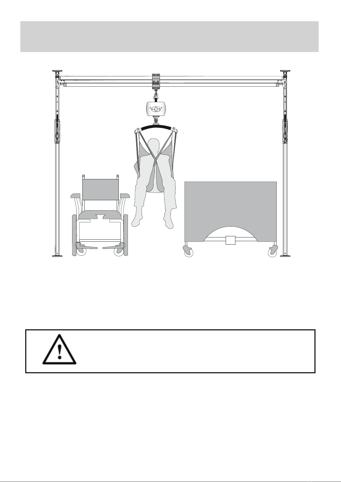
Drawing showing front view of a common
Easy
Fit System set up in a room. In this drawing arrangement,
a general placement of a bed is shown in relationship to the system. Notice that there is still room for a
wheelchair to be placed beside the bed.
DO NOT GO OUTSIDE OF THIS RANGE OF PLACEMENT OTHERWISE
INJURY MAY OCCUR TO THE OPERATOR OF THE LIFT AND/OR THE
INDIVIDUAL BEING TRANSFERRED, AND/OR THE EASY FIT SYSTEM

9
Before using the Easy Fit System, the top plate, bottom plate, supporting posts and adjustable
track must be visually checked to ensure that there are no missing parts or unusual wear and tear.
Top plate and Bottom plate should be cleaned and dry with wet cloth before installation.
Should anything look unusual contact your local dealer prior to use. Failure to comply with this caution
could result in serious injury to the operator, the individual being lied and/or damage to the Easy Fit
System and/or port-able li unit.
5. Assembly
1. Place the circular Bottom Plate on the
oor in required position for use
2. Insert the bottom of the Support Post to
the Bottom Plate
3. Insert the Top Plate onto the top of the
Support Post
4. Depress the red button and release the
Safety Lock

10
Assembly continued ......
5. Depress the Ratchet Button to release the
Lever, then push the Lever up until it meets
the Magnet Symbol. Note: Pushing down on
the top part of the Support Post may help to
release the Lever
6. Push the top part of the Support Post
upwards until the Top Plate compresses
against the ceiling. Push until you hear two
clicks on the ratchet
7. Open the Post Level (opposite the Safety
Lock) and check that the bubble is within the
central circle by adjusting the position of the
Support Post
8. Pull the lever down until it at to the
support leg and clicks into place
Table of contents
Other Mackworth Mobility Aid manuals

Mackworth
Mackworth TA400 User manual

Mackworth
Mackworth TA400 User manual

Mackworth
Mackworth SA180 User manual

Mackworth
Mackworth TA180 User manual

Mackworth
Mackworth SA180 User manual

Mackworth
Mackworth M400 User manual

Mackworth
Mackworth M180 User manual

Mackworth
Mackworth SA400 User manual

Mackworth
Mackworth 180 Mobile Hoist User manual

Mackworth
Mackworth M Series User manual
Popular Mobility Aid manuals by other brands

Rhythm Healthcare
Rhythm Healthcare B3800F manual

AMF-BRUNS
AMF-BRUNS PROTEKTOR installation manual

Drive DeVilbiss Healthcare
Drive DeVilbiss Healthcare OTTER Instructions for use

Rhythm Healthcare
Rhythm Healthcare C500U Assembly and Fitting Instructions

Lumex
Lumex RJ4200A manual

Rebotec
Rebotec Jumbo user manual