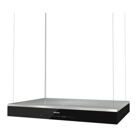
LuxeAir RH006 Installation guide

Use, Care, and Installation Guide
Model number:
Serial Number:
READ AND SAVE THESE INSTRUCTIONS
DEC19.0401
DRH00630BS
DRH00636BS
DRH00830BS
DRH00836BS
DRH00930BS
DRH00930BBS
DRH00936BS
DRH00936BBS


1
SAFETY NOTICE ................................................................. 2-3
LIST OF MATERIALS....................................................... 4
INSTALLATION
Ducting Calculation Sheet....................................... 5
Mounting Height & Clearance................................ 6
Ducting Options ........................................................... 7
Hood Specications RH006 ................................... 8
Hood Specications RH008 ................................... 9
Hood Specications RH009 ................................... 10
Mounting the Hood RH006 ..................................... 11
Mounting the Hood RH008 ..................................... 12
Mounting the Hood RH009 ..................................... 13
Ductless Recirculating .............................................. 14
FEATURES & CONTROLS
Electronic Controls ..................................................... 15
MAINTENANCE
Hood and Filter Cleaning......................................... 16
CFM SELECT................................................................................. 17
WIRING DIAGRAMS................................................................... 18
TROUBLESHOOTING................................................................ 19
LIST OF PARTS AND ACCESSORIES .............................. 20
WARRANTY.................................................................................... 21
Table of Contents

Important Safety Notice
READ AND SAVE THESE INSTRUCTIONS
2
WARNING
TO REDUCE THE RISK OF FIRE OR ELECTRIC SHOCK, DO NOT USE THIS FAN WITH ANY SOLID-STATE CONTROL DEVICE.
WARNING
TO REDUCE THE RISK OF FIRE ELECTRIC SHOCK, OR INJURY TO PERSONS, OBSERVE THE FOLLOWING:
a. Use this unit only in the manner intended by the manufacturer, if you have questions, contact the manufacturer.
b. Before servicing or cleaning unit, switch power o at service panel and lock panel to prevent power from being switched on accidentally.
When the service disconnecting means cannot be locked, securely fasten a prominent warning device, such as a tag, to the service
panel.
CAUTION
For general ventilating use only. Do not use to exhaust hazardous or explosive materials and vapors. Take care when using cleaning
agents or detergents. Suitable for use in household cooking area.
WARNING
TO REDUCE THE RISK OF RANGE TOP GREASE FIRE:
a. Never leave surface units unattended at high settings. Boilovers cause smoking and greasy spillovers that may ignite. Heat oils slowly
on low or medium settings.
b. Always turn hood ON when cooking at high heat or when aming food
c. Clean ventilating fans frequently. Grease should not be allowed to accumulate on fan or lter.
d. Use proper pan size. Always use cookware appropriate for the size of the surface element.
e. Keep fan, lters and grease laden surfaces clean.
f. Use high setting on hood only when necessary.
g. Don’t leave hood unattended when cooking.
h. Always use cookware and utensils appropriate for the type of and amount of food being prepared.
WARNING
TO REDUCE THE RISK OF INJURY TO PERSONS IN THE EVENT OF A RANGE TOP FIRE, OBSERVE THE FOLLOWING:
a. SMOTHER FLAMES with a close-tting lid, cookie sheet, or metal tray, then turn o the burner. BE CAREFUL TO PREVENT BURNS.
If the ames do not go out immediately, EVACUATE AND CALL THE FIRE DEPARTMENT.
b. NEVER PICK UP A FLAMING PAN – You may be burned.
c. DO NOT USE WATER, including wet dishcloths or towels – a violent steam explosion will result.
d. Use an extinguisher ONLY if:
1. You know you have a Class ABC extinguisher, and you already know how to operate it.
2. The re is small and contained in the area where it started.
3. The re department is being called.
4. You can ght the re with your back to an exit
WARNING
TO REDUCE THE RISK OF FIRE, ELECTRIC SHOCK OR INJURY TO PERSONS, OBSERVE THE FOLLOWING:
a. Installation work and electrical wiring must be done by qualied person(s) in accordance with all applicable codes and standards.
Including re-rated construction.
b. Sucient air is needed for power combustion and exhausting of gases through the ue (chimney) of fuel burning equipment to prevent
back-drafting. Follow the heating equipment manufacturer’s guideline and safety standards such as those published by the National
Fire Protection Association (NFPA) and the American Society for Heating, Refrigeration and Air Conditioning Engineers (ASHRAE) and
the local code authorities.
c. When cutting or drilling into wall or ceiling, do not damage electrical wiring and other hidden utilities.
d. Ducted fans must always vent to the outdoors.
e. NEVER place a switch where it can be reached from a tub or shower.
f. Make sure the power is o before installing, wiring or maintenancing.

Important Safety Notice
3
WARNING
TO REDUCE THE RISK OF FIRE, USE ONLY METAL DUCTWORK.
CAUTION
To reduce risk of re and to properly exhaust air outside - Do not vent exhaust air into spaces within walls, ceilings,
attics, crawl spaces or garages.
Not for use over an outdoor grill.
This hood is not intended to be used as a shelf.
OPERATION
Always leave safety grilles and lters in place. Without these components, operating blowers could catch onto hair, ngers
and loose clothing.
The manufacturer declines all responsibility in the event of failure to observe the instructions given here for installation,
maintenance and suitable use of the product. The manufacturer further declines all responsibility for injury due to
negligence and the warranty of the unit automatically expires due to improper maintenance.
ELECTRICAL REQUIREMENTS
Important:
Observe all governing codes and ordinances.
It is the customer’s responsibility:
- To contact a qualied electrical installer.
- To assure that the electrical installation is adequate and in conformance with National Electrical Code, ANSI/NFPA 70
latest edition* or CSA standards C22.1-94, Canadian Electrical Code, Part 1 and C22.2 No.0-M91 - latest edition** and
all local codes and ordinances.
If codes permit and a separate ground wire is used, it is recommended that a qualied electrician determine that the
ground path is adequate.
Do not ground to a gas pipe.
Check with a qualied electrician if you are not sure the range hood is properly grounded.
Do not have a fuse in the neutral or ground circuit.
*National Fire Protection Association Batterymarch Park, Quincy, Massachusetts 02269
** CSA International 8501 East Pleasant Valley Road, Cleveland, Ohio 44131-5575
This appliance requires a 120V 60Hz electrical supply and connected to an individual properly grounded branch circuit
protected by a 15 or 20 ampere circuit breaker or time delay fuse. Wiring must be 2 wire with ground. Please also refer to
Electrical Diagram on product.
A cable locking connector (not supplied) might also be required by local codes. Check with local requirements, purchase
and install appropriate connector if necessary.
RH00630BS, RH00636BS - 320 Watts, 2.6 Amps
RH00830BS, RH00836BS - 320 Watts, 2.6 Amps
RH00930BxS, RH00936BxS - 320 Watts, 2.6 Amps
Power consumption shown above is the default power specs. Hoods with CFM Selector Technology enabled will consume
less power. See wiring diagram at the end of this manual for more information.
Cancer and Reproductive Harm - www.P65Warnings.ca.gov
WARNING:
Prop. 65 Warning for California Residents

4
PARTS NOT SUPPLIED
- Ducting, conduit and all installation tools
- Cable connector (if required by local codes)
- Extension duct cover accessory
- Recirculating kit accessory
HARDWARE PACKAGE CONTENTS
PARTS SUPPLIED
1 - Hood with internal blower
1 - Duct cover wall bracket
1 - Duct cover assembly (top and bottom)
1 - Hardware package
1 - 6” round backdraft damper (pre-installed)
1 - 5W LED Light Strip
2 - Baffle Filters
RH00630BS, RH00636BS
(4) #6 x 1-1/2” (2) #6 x 1” (2) 4 x 8mm (3) Wire Nuts
RH00830BS, RH00836BS
(3) #6 x 1-1/2” (2) #6 x 1” (2) 4 x 8mm (3) Wire Nuts
RH00930BxS, RH00936BxS
(2) 4 x 31mm(3) #6 x 1” (2) 4 x 8mm (3) Wire Nuts
List of Materials

5
Duct pieces To tal
Equivalent number
length x used =
3-1/ 4” x 10”
Rect.,
straight
1 Ft. x ( ) =Ft.
3-1/ 4” x 10”
Rect.to
6” round
transition
5 Ft. x ( ) =Ft.
3-1/ 4” x 10”
Rect.to
6” round
transition
900 elbow
20 Ft. x ( ) =Ft.
6”, 7”, 8”, 10”
Round,
900
15 Ft.
x ( ) =Ft.
6”, 7”, 8”, 10”
Round,
450
9 Ft. x ( ) =Ft.
Ft.
6”, 7”, 8”, 10”
Round,
straight
1 Ft. x ( ) =Ft.
Subtotal column 1 =
Duct pieces To tal
Equivalent number
length x used =
6”, 7”, 8”, 10”
Round, wall
cap with
damper
30 Ft. x ( ) =Ft.
Ft.
Ft.
Ft.
6”, 7”, 8”, 10”
Round
roof cap
30 Ft. x ( ) =Ft.
Subtotal column 2 =
Subtotal column 1 =
Total ductwork =
Maximum Duct Length: For satisfactory air movement,
the total duct length
should not exceed 100 equivalent feet.
6” round to
3-1/ 4” x 10”
rect.
transition
1 Ft. x ( ) =Ft.
6” round to
3-1/ 4” x 10”
rect.
transition
900 elbow
16 Ft. x ( ) =Ft.
7” round to
3 1/ 4” x 10”
rect.
transition
8 Ft. x ( ) =Ft.
7” round to
3-1/ 4” x 10”
rect.
transition
900 elbow
23 Ft. x ( ) =Ft.
elbow
elbow
7” to 6” or
8” to 7” Round
tapered
reducer
25 Ft. x ( ) =Ft.
3-1/ 4” x 10”
Rect.900
elbow
15 Ft. x ( ) =Ft.
3-1/ 4” x 10”
Rect.450
elbow
9 Ft. x ( ) =Ft.
3-1/ 4” x 10”
Rect.900
flat elbow
24 Ft. x ( ) =Ft.
3-1/ 4” x 10”
Rect.
wall cap
with damper
30 Ft. x ( ) =Ft.
Ft. x ( ) =Ft.
15
6”, 7“, 8”
Round
in-line
damper
Installation – Ducting Calculation Sheet

Installation – Mounting Height & Clearance
6
DUCTING
A minimum of 6” round duct must be used to
maintain maximum air ow eciency.
Always use rigid type metal ducts only. Flexible
ducts could restrict air ow by up to 50%.
Use calculation worksheet to compute total duct
work (Page 5).
ALWAYS, when possible, reduce the number of
transitions and turns. If a long duct run is required,
increase duct size from 6” to 7” or 8”.
If turns or transitions are required: Install as far
away from duct opening and as far apart between
the two transitions as possible.
Minimum mount height between range top to hood
bottom should be no less than 24”.
Maximum mount height should be no higher than
34”.
It is important to install the hood at the proper
mounting height. Hoods mounted too low could
result in heat damage and re hazard; while hoods
mounted too high will be hard to reach and will
loose performance and eciency.
If available, also refer to range manufacturer’s
height clearance requirements and recommended
hood mounting height above range. Always check
your local codes for any dierences.
Duct cover extension kit available for ceiling
heights up to 12 feet. Turn to page 20 for part
number and ordering information.
DAMAGE-SHIPMENT / INSTALLATION:
• Please fully inspect unit for damage before
installation.
• If the unit is damaged in shipment, return the
unit to the store in which it was bought for
repair or replacement.
• If the unit is damaged by the customer, repair
or replacement is the responsibility of the
customer.
• If the unit is damaged by the installer (if other
than the customer), repair of replacement must
be made by arrangement between customer
24” min.
34” max.
min. A
min. B
max. C
min. D
min. E
max. F
Standard Extension
Hood Heights Duct Cover Duct Cover
minimum ducted (A) 26” 41“
minimum recirculating (B) 31” 45-1/2“
maximum (C) 49” 78-1/2”
Ceiling Heights
minimum ducted (D) 86” 101“
minimum recirculating (E) 91” 105-1/2“
maximum (F) 119” 148-1/2”
36”
Standard Extension
Hood Heights Duct Cover Duct Cover
minimum ducted (A) 27” 43“
minimum recirculating (B) 31” 47“
maximum (C) 48” 81”
Ceiling Heights
minimum ducted (D) 87” 103“
minimum recirculating (E) 91” 107“
maximum (F) 118” 151”
RH008
RH009
Standard Extension
Hood Heights Duct Cover Duct Cover
minimum ducted (A) 27-1/2” 46-1/2“
minimum recirculating (B) 32” 50-1/2“
maximum (C) 42-1/2” 80”
Ceiling Heights
minimum ducted (D) 87-1/2” 106-1/2“
minimum recirculating (E) 92” 110-1/2“
maximum (F) 104-1/2” 150”
RH006

7
and installer.
WARNING FIRE HAZARD
NEVER exhaust air or terminate duct work into spaces between walls, crawl spaces, ceiling, attics or garages.
All exhaust must be ducted to the outside, unless using the recirculating option.
Use single wall rigid metal ductwork only.
Fasten all connections with sheet metal screws and tape all joints w/ certied Silver Tape or Duct Tape.
Some Ducting Options
Installation – Ducting Options
side wall cap
w/ gravity damper
Soffit or crawl space
Roof Pitch w/
Flashing & Cap
ductless
recirculating
side wall cap
w/ gravity damper

8
Installation – Hood Specication RH006
1"
11
8
"
13
16
"
37
16
"
29
15
16
"
83
4
"
63
4
"
12"
19
3
4
"
35 7
8
"
,
Standard Duct Cover
Min. ducted 27
1/2
”
Min. recirc. 32”
Max. ducted 42
1/2
”
RHEX001S Extension
Min. ducted 46
1/2
”
Min. recirc. 50
1/2
”
Max. ducted 80”
This manual suits for next models
10
Other LuxeAir Ventilation Hood manuals