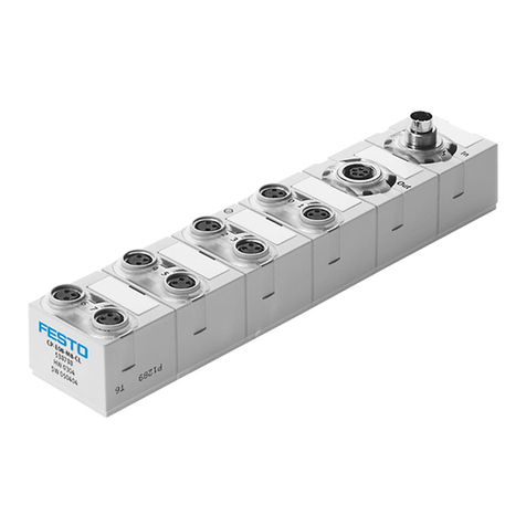
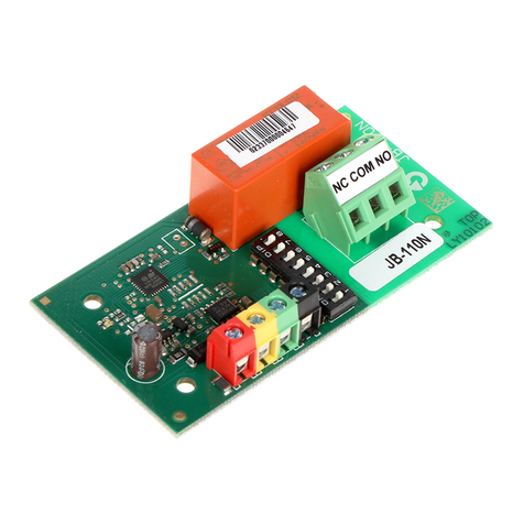
LucidControl DI8 User manual

LucidControl DI4/DI8, User Manual (2.0) 2018-08-04
Page 1 of 29
User Manual
LucidControl DI4/DI8
4/8 Channel Digital Input USB Module

LucidControl DI4/DI8, User Manual (2.0) 2018-08-04
Page 2 of 29
1Introduction
This document describes the functionality of the LucidControl DI4/DI8 USB module with
4/8 digital inputs controllable via Universal Serial Bus.
A general description of the complete LucidControl product family can be found in the
document LucidControl User Manual.
This document explains the topics that are specific to the DI4/DI8 module.
2Setup and Installation
Fig. 1 shows the sketch of the Digital Input DI8 module with
8 digital input channels.
The IO channels are split into the lower and the upper IO
connectors.
The lower IO connector (IO1 to IO8) provides terminals for
the channels DI0 to DI3.
The upper IO connector (IO9 to IO16) is mounted on DI8
module only. It provides terminals for the channels DI4 to
DI7.
The intended use of the DI4/DI8 module is the acquisition of digital signals. The
module must only be used for the intended use.
For this device it is explicitly stated that no potential (e.g. voltage) of more than
30V must be applied to any connector of the module. The modules must only be
used within the specified conditions.
Fig. 1 Digital Input Module

LucidControl DI4/DI8, User Manual (2.0) 2018-08-04
Page 3 of 29
2.1 Configurations
Digital inputs have by nature only two states –they can be either LOW or HIGH. In order to
be compatible with different voltage signals, the DI4/DI8 module is available with three
threshold levels:
Threshold Level
VLowMax
VHighMin
5 V
2.5 V
3.5 V
10 V
6.0 V
8.5V
24 V
16.0 V
21.0 V
Tab. 1 Input Threshold Level
The table above shows the configurations and their input characteristics. All modules have
a voltage range below VLowMax which is treated as LOW state, and a voltage range above
VHighMin representing a HIGH state.
Input level restrictions
The range between VLowMax and VHighMin is forbidden by means that the state cannot be
determined correctly.
Example
For typical automation applications, 24 V inputs are often used. When interfacing 24 V
signals it needs to be ensured that in case of a LOW state a voltage equal or below 16 V is
applied to the input. Detecting a HIGH state requires a voltage of equal or higher than 21
V. For the range between 16 V and 21 V is used as a hysteresis which means that a once
set input is HIGH until the input voltages is lower than 17V.
2.2 Interface and Interconnection
2.2.1 USB Connection
Note
Please consider that the total power of one USB port is limited to 500 mA.
Note
Using an active USB-Hub with its own power supply allows the connection of additional
devices in the case that the host is not able to supply them.
LucidControl DI4/DI8 module is rated with a maximum current of 40 mA.

LucidControl DI4/DI8, User Manual (2.0) 2018-08-04
Page 4 of 29
2.2.2 IO Connection
The LucidControl DI4/DI8 module is equipped with 4 opto-insulated and potential-
insulated inputs.
Fig. 2 shows the interconnection of the DI4 module in a typical
application.
The input signals are represented by voltage sources applying a
voltage within the valid threshold range to the inputs.
The terminals IO1, IO3, IO5, IO7 (and also IO9, IO11, IO13, IO15
for the DI8 module) are the positive voltage inputs.
The terminals IO2, IO4, IO6, IO8 (and IO10, IO12, IO14, IO16 for
the DI8 module) are the negative voltage inputs.
Fig. 3 illustrates the principle how the digital input
works. The signal applied to the terminals 1 and 2
sources an opto-coupler which insulates the electronic
of the module from the input signal.
All inputs are floating by means that they have no
common contacts (like ground) and are working
independently.
Applying a voltage above VHighMin between the input terminals 1 (resp. 3, 5, 7, ...) and 2
(resp. 4, 6, 8, ...) sources the LED of the opto-coupler and makes its transistor conductive
resulting in a digital HIGH state level. If the voltage is below VLowMax is applied this results in
a LOW state level.
All inputs are protected against overvoltage. Applying a voltage higher than
VInMax = 30 V may damage the input.
All inputs are protected against reverse polarity. Applying a voltage lower than –
VInMax = -30V may damage the input.
Fig. 2 Digital Input Module
Connection
Fig. 3 Digital Input Principle

LucidControl DI4/DI8, User Manual (2.0) 2018-08-04
Page 5 of 29
2.2.3 Isolation of USB Interface (-ISO option)
Fig. 4 DI4 Module with isolated USB Interface
DI4 and DI8 modules are optionally available with isolated USB interface (-ISO option).
Fig. 4 shows the DI4 module with isolated USB interface.
The isolation consists of a galvanic barrier (red area) that isolates the IO module entirely
from the USB data lines and power supply lines. An isolated DC/DC converter separates the
power supply.
The main purpose of the isolated LucidControl module is the separation of the IO module
from the data processing equipment (e.g. the host computer). Non-Isolated IO modules
are conductive connected to the USB port also sharing a common ground line.
Harsh or noisy environments (e.g. with disturbances or long cables) may cause
measurement errors or malfunction of the data processing equipment or the IO module
caused by ground loops. This can be solved by the isolation of the USB port.
Another aspect is the protection of the data processing equipment from overvoltage. If for
example a voltage above the limits of the module is applied to the terminals this can
damage the module and the data processing equipment also.
The isolation limits the possible damage to the IO module itself.
USB isolation can be an option if a higher protection level required or if LucidControl IO
modules are operating in harsh environments.
Even when the isolation protects the data processing equipment from overvoltage
damage it does not protect from voltages > 50V!

LucidControl DI4/DI8, User Manual (2.0) 2018-08-04
Page 6 of 29
Note:
All inputs of the DI4/DI8 module are isolated by an opto-coupler (Fig. 3).

LucidControl DI4/DI8, User Manual (2.0) 2018-08-04
Page 7 of 29
2.3 Setup of Hard- and Software
Setting up LucidControl hardware is very easy:
1Ensure that no signal is applied to the IO Connector
2Connect LucidControl via USB with the computer
3Applies for Microsoft Windows older than Windows 10 only: The system asks for an
installation file. This is not a driver but only an information file (INF). The file can be
downloaded from our website www.lucid-control.com/downloads
That’s all. LucidControl switches the green power LED on and the module is ready
for usage.
2.3.1 Windows
As mentioned the installation under Microsoft Windows (older than Windows 10) requires
the information file.
After finished installation the Windows Device Manager contains a new serial port (COM).
The module can be accessed using this port.
Note
Even if more than one module is connected to a computer Windows ensures that the same
serial port number is assigned to the module(s) after restart.
2.3.2 Linux
Despite to Windows installation under Linux the module is usable immediately after
connection without any additional steps. Linux installs /dev/ttyACM devices for any
module connected to the computer.
Note
By default Linux cannot ensure that the same /dev/ttyACM device is assigned to the same
module on restart. But as long as only one module is connected to the computer it is
ensured that it is accessible via /dev/ttyACM0.
This problem can be solved by the LucidIoCtrl command line tool which can create static
devices always pointing to a specific module. Moreover the device can be given useful
names e.g. dev/digitalIoKitchen.

LucidControl DI4/DI8, User Manual (2.0) 2018-08-04
Page 8 of 29
2.3.3 Get command line LucidIoCtrl
LucidIoCtrl command line tool can be downloaded from our website:
www.lucid-control.com/downloads
This page provides the command line tool LucidIoCtrl for different architectures.
After downloading the program can be stored in a folder of choice.
Please see the section 3 of the general LucidControl User Manual for more information
about this helpful tool.
2.3.4 Ready for Take-Off
After the module was installed successfully (if it was necessary at all) the green Power LED
is switched on signaling that the module is ready for use.
Since the module was preconfigured for standard input mode, it can be used without
further configuration. The following examples demonstrate the functionality of the module
by using the LucidIoCtrl command line tool.
Windows Examples:
For all examples it is assumed that the module is connected to COM1.
Reading the values of all 4 input channels
LucidIoCtrl –dCOM1 –tL –c0,1,2,3 –r [ENTER]
-> CH0:00 CH1:00 CH2:00 CH3:00
Linux Examples:
For all examples it is assumed that the module is connected to /dev/ttyACM0.
Reading the values of all 4 input channels
LucidIoCtrl –d/dev/ttyACM0 –tL –c0,1,2,3 –r [ENTER]
-> CH0:00 CH1:00 CH2:00 CH3:00

LucidControl DI4/DI8, User Manual (2.0) 2018-08-04
Page 9 of 29
3Module Operation
3.1 Operation Modes
This section explains the operation of the different input modes and gives examples how
to configure and use them.
Each of the inputs of the module can work in one of the following modes:
Reflect Mode
Rising Edge Mode
Falling Edge Mode
Count Mode
In all modes the input values are captured and evaluated after a stable signal has been
detected.
Physical input value inversion:
Digital inputs distinguish between physical and logical input state. The physical state is
represented by the voltage applied to the input. The logical state is calculated by the input
handling and may be identical to the physical state.
In case of input inversion is enabled by setting inDiInverted to “on” the logical value is
inverted in relation to the physical input. This means that applying a voltage above VHighMin
results in a HIGH physical input value but a LOW logical input value.
All input modes support the inversion of physical input value, but in practice it is useful for
Reflect Mode only.

LucidControl DI4/DI8, User Manual (2.0) 2018-08-04
Page 10 of 29
3.1.1 Reflect Mode
Reflect Mode gives access to the logical input value directly.
Fig. 5 illustrates the processing of the inputs in Reflect
Mode.
As soon as the rising edge of the input signal is detected
it must remain stable over the interval TScan. After TScan
has passed the input signal is captured and the input
value is set to the corresponding value.
In the case that a pulse is shorter than TScan the pulse is
not valid. This scenario is shown in the first pulse of Fig.
6. While the first rising edge starts the scan timer the
falling edge stops it (indicated by the gray TScan interval)
resulting in canceling the pulse detection.
Since the second pulse is longer than TScan it is evaluated
as valid value.
Filtering digital signals and validating their stability can be used to surpress errors and to
make the recognition of digital inputs more relyable.
The scan interval TScan is configurable by changing the parameter inDiScanTime which is
described in section 3.3.4 .
Fig. 7 illustrates the same input signal as Fig. 5 but with
inDiInverted set to “on” resulting in logical input value
being inverted in relation to the physical input value.
Fig. 7 Inverted Reflect Mode
Fig. 5 Reflect Mode Input Processing
Fig. 6 Reflect Mode Pulse Width
This manual suits for next models
1
Table of contents