Louisville AA2210 User manual

ATTIC LADDER
INSTALLATION
INSTRUCTIONS
INSTRUCCIONES DE INSTALACIÓN DE LA ESCALERA DE ÁTICO
English / Inglés: Page 1 / Página 1 |Español / Spanish: Página 12 / Page 12
MODELS/MODELOS: AA2210 | AA2510 | WA2210

WARNING
Before you start installing your new Louisville Ceiling Mounted Folding Attic Ladder, you
must read and understand the following:
1. For residential use only. Not for use in a commercial or industrial setting.
2. Installation requires two people.
3. Do NOT remove plastic straps holding the ladder sections together until instructed.
4. Check the ceiling height to make sure the ladder length is correct. If the ladder is too short,
return it to the point of purchase for an exchange. Under no circumstance is any folding attic ladder
to be used when the ceiling–to–floor measurement exceeds the maximum ceiling height as indicated
for the Ceiling Mounted Folding Attic Ladder you are installing (See “Ceiling Height Range”column in
table 1).
5. This folding attic ladder is completely assembled and is ready for installation.
Do not disassemble it to install.
6. The springs / gas cylinders on this folding attic ladder are under pressure. Do not attempt to remove or
replace before installation.
7. Prior to installation, verify that all fasteners are properly tightened. Re–check these periodically after
initial installation.
8. Make sure there is no wiring or piping that the saw or drill can come in contact with during installation.
9. Opening or standing on the folding attic ladder’s climbing sections prior to properly fastening to ceiling
joists could cause serious bodily injury.
10. Verify that the unit meets local building codes and that the intended area of installation is of sufficient
strength to be used for a walking or working surface.
11. If the home has roof trusses, do not cut the ceiling joists without consulting an engineer for approval.
12. Before installation, read all the instruction labels on the folding attic ladder.
13. Improper installation could result in serious bodily injury.
14. Do not attempt to open the door prior to installation.
15. Only use the lag screws provided for the permanent installation step.
16. Follow the “Adjust The Ladder Height”instructions on Step 3 for proper trimming instructions.
17. Annually lubricate (spray silicon recommended) pivot points of right and left folding arm mechanism
(power arm assembly) to provide smooth, long–lasting operation.
1

Included with your Folding Attic Ladder:
WOOD SERIES
NO. ITEM QTY
1Pull cord 36”1
2Deck screw 2 ½”8
3Lag screw 3”10
4 Plastic Shoe 2
5Wood screw 1”4
FIGURE 1: Wood series
ALUMINUM SERIES
NO. ITEM QTY
1Pull cord 36”1
2Deck screw 2 ½”8
3Lag screw 3”10
4Aluminum Feet
(mounted on ladder) 2
5¼”Nuts
(mounted on ladder) 4
6Bolts ¼”x ¾”large
(mounted on ladder) 4FIGURE 2: Aluminum series
MATERIALS REQUIRED
1. Stepladder 7. Drill
2. Hammer 8. Drill bit ⁄”,⁄”
3. Adjustable wrench 9. Phillips screw driver
4. Tape measure 10. (2) Temporary boards 1”x 4”x 32”
5. Hand saw 11. Shims
6. Hack saw
2

INSTALLATION INSTRUCTIONS FOR WOOD MODELS AND FOR ALUMINUM MODELS
READ INSTRUCTIONS AND WARNINGS COMPLETELY BEFORE STARTING
IMPORTANT: Do not open folding attic ladder until instructed to in
step number 3.
FOLDING ATTIC LADDER LOCATION:
Allow ample room for the swing clearance and
the landing space of the folding attic ladder when
it is opened (see Figure 3 and table 1). Locate the
folding attic ladder rough opening so that when
you enter the storage area, you will have adequate
head clearance.
You must have a rough opening of 22 ½”x 54”or
25 ½”x 54”. If not, proceed to the appendix for
framing instructions.
MODEL
ROUGH
OPENING
CEILING HT.
RANGE “A”
LANDING
SPACE “B”
SWING
CLEARANCE “C”
AA2510 25 ½”x 54”7’ 8”– 10’3”67”74”
AA2210 22 ½”x 54”7’8”– 10’3”67”74”
WA2210 22 ½”x 54”7’11”– 10’3”64 ½”74”
TABLE 1
B
LANDING SPACE
C
SWING CLEARANCE
A
CEILING
HEIGHT
RANGE
FIGURE 3
3

STEP 1: PRELIMINARY INSTALLATION INSTRUCTIONS
A. Attach temporary supports “A”and “B”with 2 ½”deck screws as shown in Figure 4.
Support “A”should be located at the end where the door hinge of the ladder will go. The
edge of support “A”should extend into the rough opening ⁄”as shown in Figure 5. Make
sure both screws penetrate header above ceiling.
B. Measuring from the inside edge of support “A”, locate and secure the inside edge of support
“B”53”from inside edge of support “A”(Figure 5). Make sure both screws penetrate
header above ceiling.
C. Thread pull cord through pre–drilled hole in door and tie a knot in end of cord. Length can
be adjusted after ladder is completely installed. Be sure the knot is large enough to not slip
through the hole.
For aluminum models, remove aluminum feet on bottom section. These will be
reinstalled in Step 3.
D. Position one person up in the attic, and position the other person in the room below. When
using stepladder make sure ladder is fully open, all feet firmly supported and user’s weight
and materials he is carrying does not exceed the load rating of the ladder.
FIGURE 5: View from above
Deck screw (2) per board
FIGURE 4: View from below
4

E. The person below will need to raise the attic ladder into the rough opening and with
assistance from person above position securely on the temporary support boards (Figure 6).
F. Make sure frame on door hinge side of ladder is pushed up against header and is centered
side to side in rough opening. Temporarily secure frame to header using two 2 ½”deck
screws (Figure 7). Do not use pre–drilled holes for deck screws. Pre–drilled holes are used in
Step 2.
CAUTION: This is only a temporary connection, NEVER climb on ladder in this condition.
G. Carefully open attic ladder door but do not unfold the climbing section until indicated in
step 3. Center and square the opposite side of attic ladder frame in the rough opening using
shims. Ensure ladder frame is square by measuring diagonals of the frame within ⁄”
(Figure 7).
H. Secure sides of ladder frame to ceiling joists with 2 ½”deck screws at shim locations
(Figure 7). Do not use pre–drilled holes for deck screws. Pre–drilled holes are used in Step 2.
Door hinge end
Shim
Header
Frame
Rough opening
FIGURE 7
FIGURE 6
Support A
Support B
5
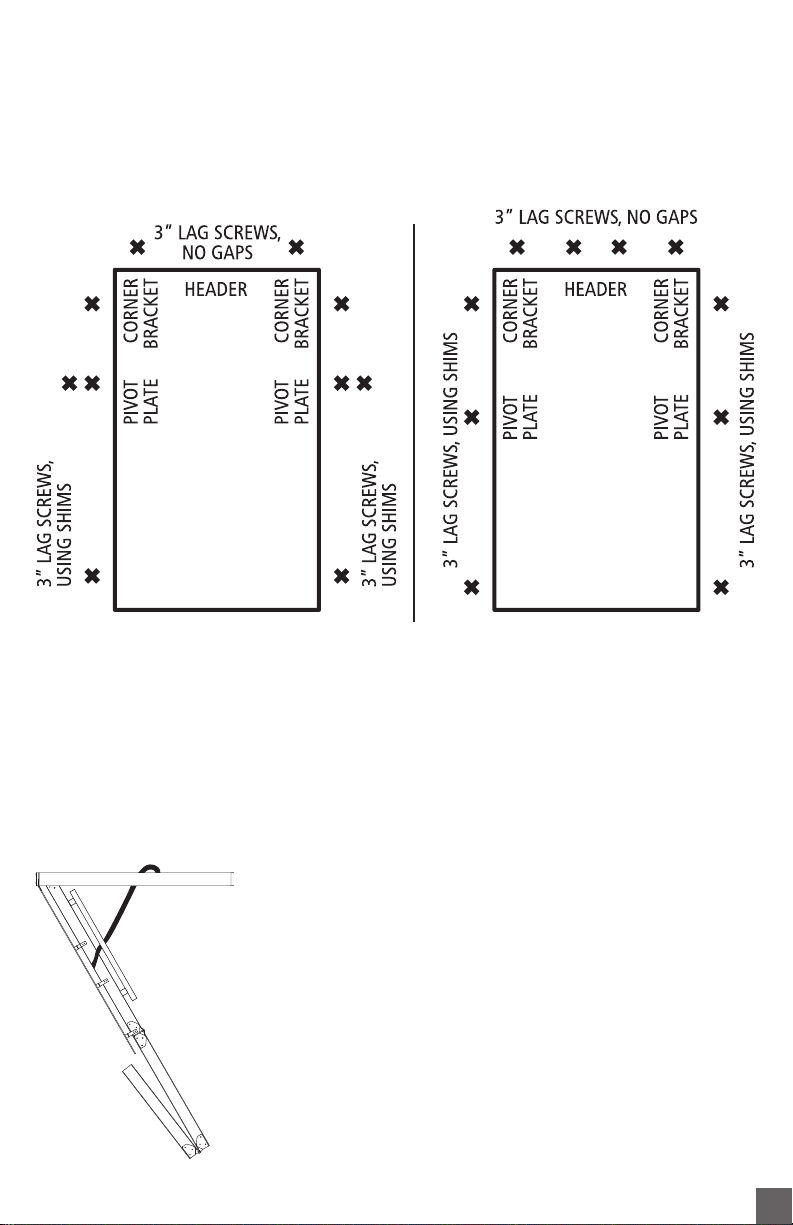
STEP 2: PERMANENT INSTALLATION
A. The ladder comes with pre–drilled holes for permanent installation at locations shown in
Figure 8 for wood models and Figure 9 for aluminum models. Shim, when necessary to fill
space between ladder frame and rough opening, at pre–drilled locations. Using ⁄”drill bit,
drill pilot holes through shim into ceiling joists and header.
B. Install the ten 3”lag screws provided, at each location to permanently secure the ladder.
C. WARNING: Never use deck or sheetrock screws in place of lag screws for
permanent installation.
D. Remove temporary boards from ceiling installed in step 1.
STEP 3: ADJUST LADDER LENGTH
Remove plastic straps holding the sections together and carefully
unfold ladder to the ground rotating bottom section behind
middle section (Figure 10).
WOOD MODELS ONLY:
(Aluminum models: skip to next section on page 8)
A. Press down on top and middle sections of the ladder to ensure
the power arms are fully extended before taking
measurements for trimming your ladder.
FIGURE 10
FIGURE 9: Aluminum seriesFIGURE 8: Wood series
6
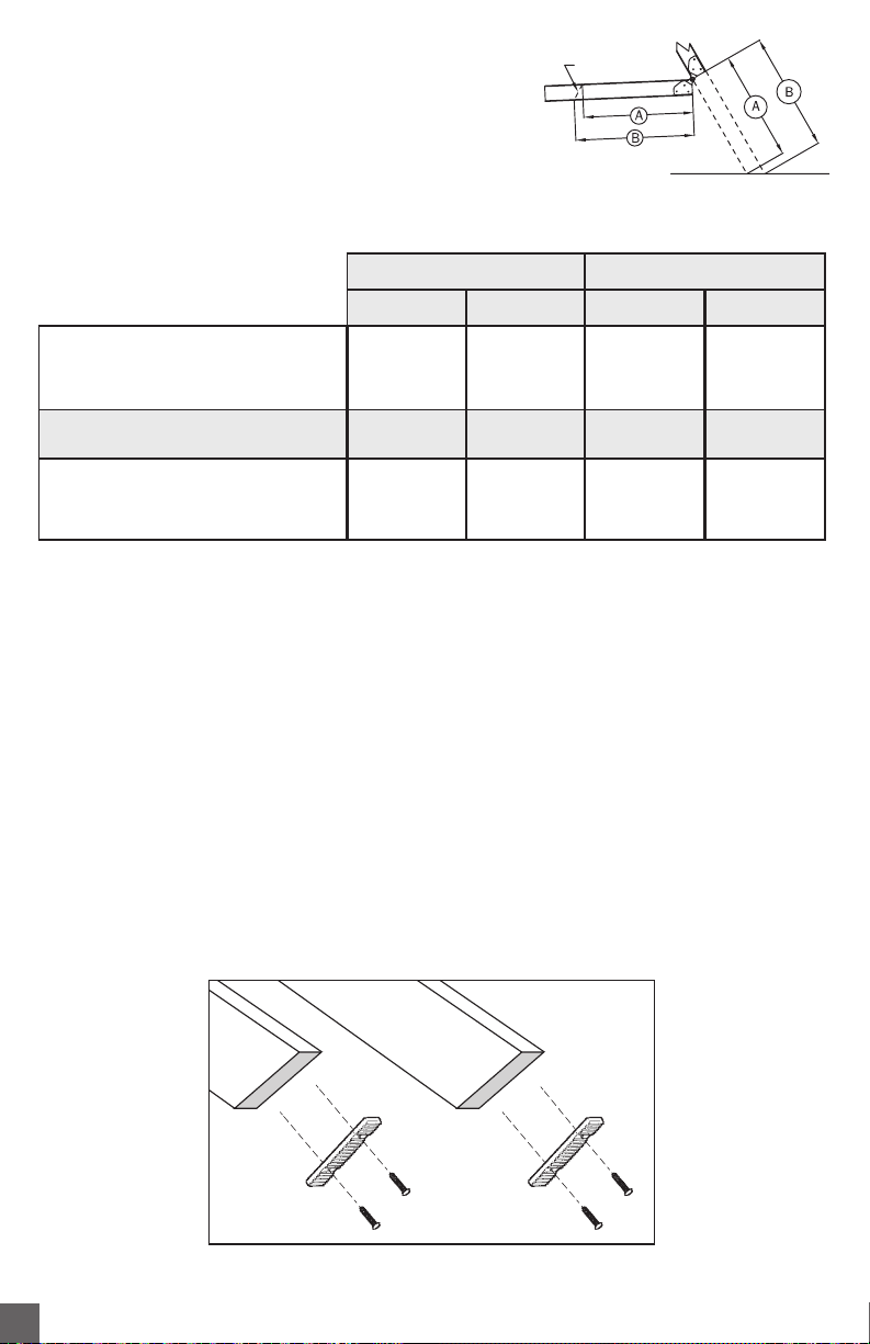
B. With a straight edge, measure distances from middle
section to floor, for both A & B lengths (Figure 11).
Record the results in the space provide in table 2. Take
measurements for both the left and right rails.
C. Complete the table: Subtract ¼”from each measurement and record in table 2 in row titled
“Cut Length”
D. Transfer these dimensions to the bottom section of the ladders right and left rails and draw
a cutting line between the two points. Trim bottom section to length using wood saw.
E. Install rubber tread to bottom ends of rail using 1”screws provided. Drill ⁄”pilot holes
into wood prior to installing screws to prevent splitting of rail (Figure 12).
Proceed to “Check the length after making your cuts”on page 9...
FIGURE 11
CUTTING
LINE
FIGURE 12
LEFT RAIL RIGHT RAIL
A B A B
Measurement to floor
Subtract for rubber shoe (-¼”) (-¼”) (-¼”) (-¼”)
Rail cut length
TABLE 2
7

ALUMINUM MODELS ONLY:
A. Using a tape measure double check the height of the ceiling.
B. Determine the location to cut the ladder and ladder feet for your ceiling height from table 3.
C. Cut the side rails and ladder feet (when required) at the appropriate line.
NOTE: The rail is not pre–marked for angle cuts required below a step (see Figure 13).
D. Press down on the climbing section to ensure that the folding arms are fully extended.
CEILING HEIGHT RAIL CUT FOOT CUT
7’8”– 7’9”* Figure 13, step #3 E
7’10”– 7’11”C E
8’– 8’2”C D
8’3”– 8’5”C no cut
8’6”Figure 13, step #2 no cut
8’7”– 9’1”B no cut
9’2”– 9’4”A no cut
9’5”– 9’10”Figure 13, step #1 no cut
9’11”– 10’3”no cut no cut
TABLE 3
*7’8”to 7’9”ceiling
heights require
drilling mounting
holes. Use foot as
drilling template.
Bottom section side rail
FIGURE 13
Aluminum feet
D E
STEP 3:
Cut not marked
on rail
STEP 2:
Cut not marked
on rail
STEP 1:
Cut not marked
on rail
C B A
8

E. Slide aluminum foot over ladder rail as shown in
Figure 14. Position so the rubber foot is in contact
with the floor.Align with closest set of predrilled
holes in rail. Attach using (2) ¼”bolts and
serrated nuts per side (included).
Check the length after making your cuts
Again, be sure the attic ladder power arms are fully extended. Trimmed correctly, your attic
ladder should look like Figure 16.Verify that there are no gaps in the section and both feet are
flat on the floor.
If the attic ladder looks like Figure 17, then both of the legs are too long and need to be
trimmed further.
If the attic ladder looks like Figure 15, then both of the legs are too short, and the attic ladder
is not safe to use. A new lower section would need to be purchased from the manufacturer.
To install trim molding leave ⁄”clearance between your door panel at the hinged end and ⁄”
on other 3 sides.
FIGURE 15 FIGURE 16 FIGURE 17
Gap No gap
Feet flush
with floor Feet ARE NOT
flush with floor
GapNo gap
FIGURE 14
For customer service, call Louisville Ladder at
1–800–666–2811 or e–mail info@louisvilleladder.com
9
Other manuals for AA2210
1
This manual suits for next models
2
Table of contents
Languages:
Other Louisville Ladder manuals


