Logicbus SDS2000X Series User manual
SDS2000X Series
Digital Oscilloscope
Quick Start

SDS2000X Series Digital Oscilloscope -I
SIGLENT TECHNOLOGIES CO., LTD. All Rights Reserved.
Declaration
SIGLENT products are protected by patent law in and outside of P.R.C.
SIGLENT reserves the right to modify or change parts of or all the specications or pricing policies at company’s sole decision.
Information in this publication replaces all previously corresponding material.
Any way of copying, extracting or translating the contents of this manual is not allowed without the permission of SIGLENT.
Note: SIGLENT is the registered trademark of SIGLENT TECHNOLOGIES CO., LTD.
Copyright
Information

II- SDS2000X Series Digital Oscilloscope
Carefully read the following safety precautions to avoid any personal injury
or damage to the instrument and any products connected to it. To avoid
potential hazards, please use the instrument as specied.
Use Proper Power Cord
Only the power cord designed for the instrument and authorized by local
country could be used.
Ground the Instrument
The instrument is grounded through the protective earth conductor of the
power cord. To avoid electric shock, please make sure the instrument is
grounded correctly before connecting its input or output terminals.
Connect the Signal Wire Correctly
The potential of the signal wire ground is equal to the earth, so do not
connect the signal wire to a high voltage.
Look Over All Terminals’ Ratings
To avoid re or electric shock, please look over all ratings and sign instruction
of the instrument. Before connecting the instrument, please read the manual
carefully to gain more information about the ratings.
Use Proper Overvoltage Protection
Make sure that no overvoltage (such as that caused by a thunderstorm) can
reach the product, or else the operator might expose to danger of electrical
shock.
Electrostatic Prevention
Operate in an electrostatic discharge protective area environment to avoid
damages induced by static discharge. Always ground both the internal and
external conductors of the cable to release static before connecting.
Keep Well Ventilation
Inadequate ventilation may cause increasing of temperature, which may
eventually damage the instrument. So keep well ventilation and inspect the
intake and fan regularly.
Avoid Circuit or Components Exposed
Do not touch exposed contacts or components when the power is on.
Use Only the Specied Fuse
Do Not Operate Without Covers
Do not operate the instrument with covers or panels removed.
General
Safety
Summary
SDS2000X Series Digital Oscilloscope -III
Warning Hazardous
Voltage
Protective
Earth Ground
Earth
Ground
Chassis
Ground
Symbols on the product. These symbols may appear on the product:
Safety Terms and Symbols
Terms on the product. These terms may appear on the product:
DANGER
WARNING
CAUTION
General Care and Cleaning
Care
Do not store or leave the instrument in direct sunshine for long periods of
time.
Notice:
To avoid damages to the instrument or probe, please do not leave them in
fog, liquid, or solvent.
Cleaning
Please perform the following steps to clean the instrument and probe
regularly according to its operating conditions.
1. Disconnect the instrument from all power sources, and then clean it with
a soft wet cloth.
2. Clean the loose dust on the outside of the instrument and probe with a
soft cloth. When cleaning the LCD, take care to avoid scratching it.
Notice:
To avoid damages to the surface of the instrument and probe, please do not
use any corrosive liquid or chemical cleanser.
Make sure that the instrument is completely dry before restarting it to avoid
short circuits or personal injuries.
Indicates direct injuries or hazards that may happen.
Indicates potential injuries or hazards that may happen.
Indicates potential damages to the instrument or other property
that may happen.
1- SDS2000X Series Digital Oscilloscope
Contents
Copyright Information.........................................................
General Safety Summary......................................................
Quick start......................................................................
The Front Panel ...............................................................
The Rear Panel.................................................................
Front Panel Overview..........................................................
User Interface..................................................................
Using Security Lock............................................................
Troubleshooting................................................................
Contact us......................................................................
I
II
2
6
7
8
17
19
20
22
SDS2000X Series Digital Oscilloscope -2
Quick start
General Inspection
1. Inspect the shipping container
Keep the damaged shipping container or cushioning material until the
contents of the shipment have been completely checked and the instrument
has passed both electrical and mechanical tests.
The consigner or carrier will be responsible for damages to the instrument
resulting from shipment. SIGLENT would not provide free maintenance or
replacement if the instrument has been damaged in shipment.
2. Inspect the instrument
If there are instruments found damaged, defective or failure in electrical and
mechanical tests, please contact SIGLENT.
3. Check the accessories
Please check the accessories according to the packing list. If the
accessories are incomplete or damaged, please contact your SIGLENT sales
representative.
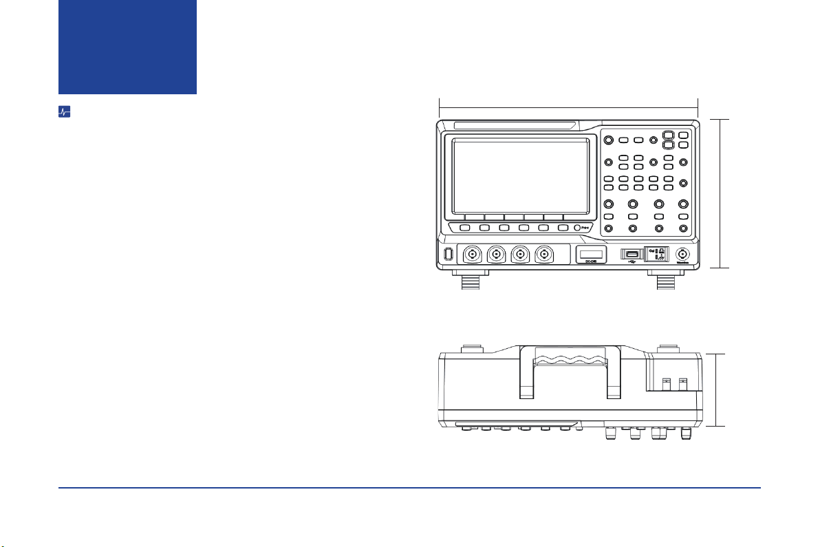
352mm
224mm 100mm
Figure 1 Front View
Figure 2 Top View

3- SDS2000X Series Digital Oscilloscope
Quick start
Adjust the Supporting Legs
Adjust the supporting legs properly to use them as stands to tilt the
oscilloscope upwards for stable placement as well as easier operation and
observation of the instrument.
Connect to AC Power Supply
The oscilloscope will accept a 100~240V, 50/60Hz or 100~120V, 400Hz AC
power supply. Please use the power cord provided with the accessories to
connect the instrument to the power source as shown in the gure below.
If at any time the fuse requires replacement, please replace only with a fuse
of the same rating as the original. If there are questions, please contact
Siglent directly.
Power
Socket
SDS2000X Series Digital Oscilloscope -4
Power-on Inspection
After plugging in the oscilloscope, turn on the power switch at the lower left corner on the front panel. During the start-up process, the instrument performs a series
of self-test items and the internal relays can be heard in operation. After the self-test, the User Interface displays immediately.
Connect the Probe
SIGLENT provides passive probes for the SDS2000X series oscilloscope. Please refer to corresponding Probe User Manual for detailed technical information.
1. Connect the BNC terminal of the probe to one of the channel BNC connectors on the front panel.
2. Connect the probe tip to the circuit point under test and the ground alligator clip of the probe to the ground terminal of the circuit.
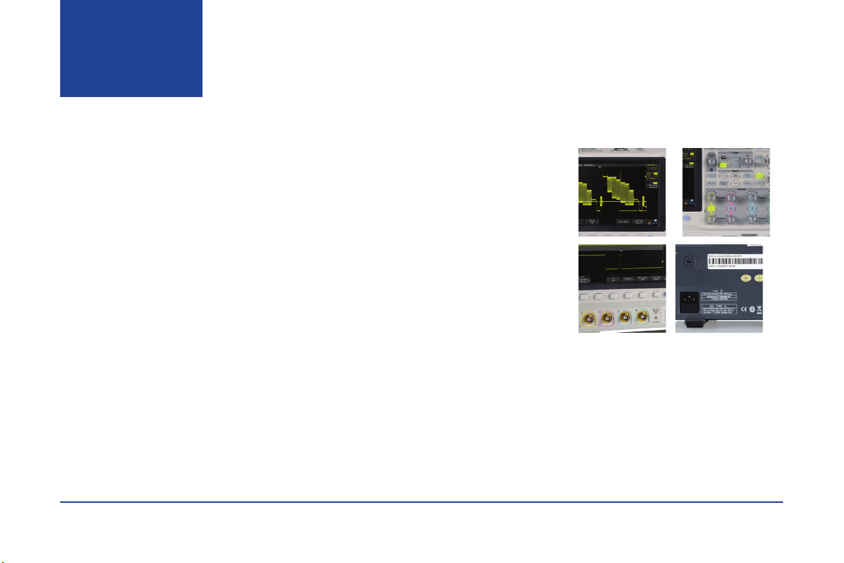
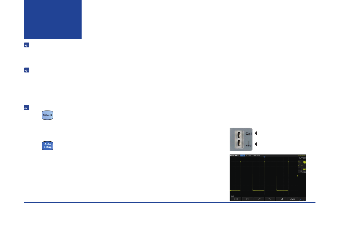
Functional Inspection
1. Press to reset the oscilloscope to its factory default setup.
2. Connect the ground alligator clip of the probe to the Ground Terminal on the front panel.
3. Use the probe to connect the CH1 Input Terminal and the Compensation Signal Output Terminal on the front
panel.
4. Press
5. Observe the waveform on the screen. In normal condition, the display should be a square waveform as shown
in the photo to the right.
6. Test the other channels in the same method. If the actual square waveforms does not match that in the photo
shown, please perform “Probe Compensation”.
Note: To avoid electric shock when using the probe, rst please make certain that the insulated wire of the probe
is in good condition, and do not touch the metallic part of the probe when it is connected to a high voltage.
Quick start
Compensation Signal Output
Terminal
Ground Terminal
5- SDS2000X Series Digital Oscilloscope
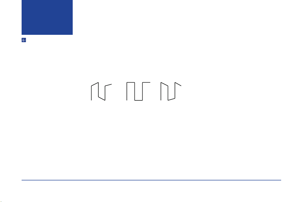
Probe Compensation
All oscilloscope probes should be properly compensated before their rst use with the oscilloscope. Non-compensated or inadequate compensated probe may cause
inaccurate measurement. The following steps illustrate the proper probe compensation procedure.
1. Perform step 1, 2 , 3 and 4 of “Functional Inspection”.
2. Check the displayed waveforms and compare them with the following gure.
3. Use a nonmetallic at-head screwdriver to adjust the low-frequency compensation adjustment hole on the probe until the waveform matches the “Compensated
Correctly” waveform above.
Quick start
Under
Compensated
Compensated
Correctly
Over
Compensated
SDS2000X Series Digital Oscilloscope -6
12 3
54
8
9
10
13 14
15
16171819
21
2023
22
11
12
6
7
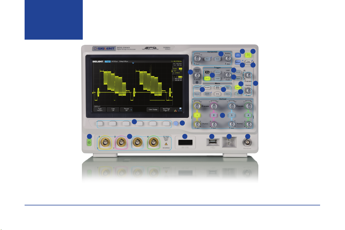
1.Horizontal Control
2.Auto Setup
3.Run/Stop
4.Default
5.Clear Sweeps
6.Universal Knob
7.Trigger Control
8.Decode Control
9.Digital Channel Control
10.Math
11.Reference
12.Math/Ref Vertical Control
13.Function Menus
14.WaveGen Control
15.Channel Vertical Control
16.WaveGen Output
17.Probe Compensation/
Ground Terminal
18.USB Host
19.Digital Inputs
20.Analog Inputs
21.Print
22.Function Menu Softkeys
23.Power On/Off
The Front
Panel
Table of contents


