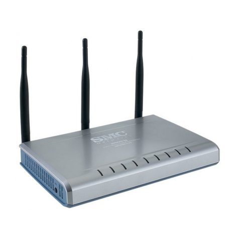
Link LKW300-21A3 User manual

LKW300-21A3
User Manual
V1.0

i
Contents
1Introduction ........................................................................................................ 1
1.1 Packing List ........................................................................................... 1
1.2 Safety Precautions ................................................................................ 1
1.3 LEDs and Interfaces .............................................................................. 2
1.4 System Requirements ........................................................................... 4
1.5 Features ................................................................................................ 5
2Hardware Installation ......................................................................................... 7
3About the Web Configuration ........................................................................... 10
3.1 Access the Router ............................................................................... 10
3.2 Wizard ................................................................................................. 11
3.3 Status................................................................................................... 25
3.3.1 System...................................................................................... 26
3.3.2 LAN........................................................................................... 26
3.3.3 WLAN ....................................................................................... 26
3.3.4 WAN ......................................................................................... 27
3.3.5 Port Mapping ............................................................................ 27
3.3.6 Statistics.................................................................................... 28
3.3.7 ARP .......................................................................................... 29
3.4 Network ............................................................................................... 30
3.4.1 LAN........................................................................................... 30
3.4.2 WAN ......................................................................................... 39
3.4.3 WLAN ....................................................................................... 47
3.5 Service................................................................................................. 60
3.5.1 DNS .......................................................................................... 60
3.5.2 Firewall ..................................................................................... 63
3.5.3 UPnP ........................................................................................ 67
3.5.4 IGMP Proxy .............................................................................. 68
3.5.5 TR-069...................................................................................... 70
3.5.6 ACL........................................................................................... 72
3.6 Advance............................................................................................... 73
3.6.1 Routing ..................................................................................... 73
3.6.2 NAT........................................................................................... 76
3.6.3 Port Mapping ............................................................................ 83

ii
3.6.4 IP QoS ...................................................................................... 84
3.6.5 SNMP ....................................................................................... 86
3.6.6 Others ....................................................................................... 88
3.7 Admin .................................................................................................. 89
3.7.1 Commit/Reboot......................................................................... 89
3.7.2 Update ...................................................................................... 90
3.7.3 System Log............................................................................... 92
3.7.4 Password .................................................................................. 92
3.7.5 Time.......................................................................................... 93
3.7.6 Logout....................................................................................... 94
3.8 Diagnostic............................................................................................ 95
3.8.1 Ping Diagnosis.......................................................................... 95
3.8.2 Traceroute Diagnosis................................................................ 96
3.8.3 OAM Loopback ......................................................................... 97
3.8.4 ADSL Statistics ......................................................................... 97
3.8.5 Diag-Test................................................................................... 98

1
1 Introduction
The LKW300-21A3 is an ADSL access device that supports multiple line modes. The
device provides high-speed ADSL broadband connection to the Internet or Intranet
for high-end users, such as net cafes and office users. The device provides high
performance access to the Internet, downlink up to 24 Mbps and uplink up to 1 Mbps.
The device supports WLAN access. It can connect to the Internet through a WLAN
AP or WLAN device. It complies with IEEE 802.11, 802.11b/g/n specifications, WEP,
WPA, and WPA2 security specifications.
1.1 Packing List
Wireless router x1
Power adapter (DC) x1
ADSL splitter x 1
Quick installation guide x1
RJ45 Cable x1
RJ11 Cable x1
CD (user manual) x1
Warranty card X1
1.2 Safety Precautions
Follow the following instructions to prevent the device from risks and damage caused
by fire or electric power:
Use volume labels to mark the type of power.
Use the power adapter packed within the device package.
Pay attention to the power load of the outlet or prolonged lines. An
overburden power outlet or damaged lines and plugs may cause electric
shock or fire accident. Check the power cords regularly. If you find any
damage, replace it at once.
Proper space left for heat dissipation is necessary to avoid damage caused
by overheating to the device. The long and thin holes on the device are

2
designed for heat dissipation to ensure that the device works normally. Do
not cover these heat dissipation holes.
Do not put this device close to a place where a heat source exists or high
temperature occurs. Avoid the device from direct sunshine.
Do not put this device close to a place where it is over damp or watery. Do
not spill any fluid on this device.
Do not connect this device to any PCs or electronic products, unless our
customer engineer or your broadband provider instructs you to do this,
because any wrong connection may cause power or fire risk.
Do not place this device on an unstable surface or support.
1.3 LEDs and Interfaces
Front Panel
Figure 1 Front Panel
The following table describes the LEDs of the device.
LEDs Color Status Description
On The initialization of the device is
successful.
Power Green
Off The device is powered off.
On
Connection between the device and
the physical layer of the office end is
established.
Blinks
slowly No signal is being detected.
ADSL Green
Blinks
quickly
The device is handshaking with the
physical layer of the office end.

3
LEDs Color Status Description
On
The Internet connection is normal in
the routing mode (for example, PPP
dial-up is successful), and no Internet
data is being transmitted.
Blinks Internet data is being transmitted in
the routing mode.
Green
Off The device is in the bridge mode.
Internet
Red On
The Internet connection fails after
successful synchronization in the
routing mode (for example, PPP
dial-up is failed).
On The LAN connection is normal and
activated.
Blinks
Data is being transmitted in the LAN
or Internet data is being transmitted
in the bridge mode.
LAN 4/3/2/1 Green
Off The LAN interface is not connected.
On The WLAN connection has been
activated.
Blinks Data is being transmitted in the
WLAN.
WLAN Green
Off The WLAN connection is not
activated.
Blinks WPS is enabled, and is waiting for
client to negotiate.
WPS Green
Off WPS is disabled.

4
Rear Panel
Figure 2 Rear panel
The following table describes the interfaces of the device.
Interface Description
WPS/WLAN
Press the button and hold it for less than 1 second to enable
WLAN.
If WLAN is enabled, press the button for more than 3
seconds, to initialize WPS negotiation.
ADSL RJ-11 interface, for connecting to the ADSL interface or a
splitter through a telephone cable.
LAN1/2/3/4 RJ-45 interface, for connecting to the Ethernet interface of a
computer or the Ethernet devices through an Ethernet cable.
Power Power interface, for connecting to the power adapter
Reset
This button is used to restore the factory default settings of
router. Keep the device powered on, and insert a needle into
the hole for more than 3 seconds, then release it. The device
restores the factory default settings of router.
1.4 System Requirements
Recommended system requirements are as follows:
A 10/100 base-T Ethernet card is installed on your PC
A hub or Switch. (connected to several PCs through one of Ethernet
interfaces on the device)

5
Operating system: Windows 98SE, Windows 2000, Windows ME, Windows
XP
Internet Explorer V5.0 or higher, Netscape V4.0 or higher, or Firefox 1.5 or
higher
1.5 Features
The device supports the following features:
Various line modes
External PPPoE dial-up access
Internal PPPoE/PPPoA dial-up access
1483Briged/1483Routed/MER/IPoA access
Multiple PVCs (up to eight) and these PVCs can be isolated from each other
A single PVC with multiple sessions
Multiple PVCs with multiple sessions
802.1Q and 802.1P protocol
DHCP server
NAPT
Static route
Firmware upgrading through Web, TFTP, or FTP
Resetting to the factory defaults through Reset button or Web
DNS
Virtual server
DMZ
Two-level passwords and usernames
Web interface
Telnet CLI
System status display
PPP session PAP/CHAP
IP filter
IP quality of service (QoS)
Remote access control
Line connection status test
Remote managing through Telnet or HTTP
Backup and restoration of configuration file

6
Ethernet interface supporting crossover detection, auto-correction, and
polarity correction
Universal plug and play (UPnP)

7
2 Hardware Installation
To connect the device, do as follows:
Step 1 Connect the ADSL interface of the device and the Modem interface of
the splitter through a telephone cable. Connect the phone to the Phone
interface of the splitter through a cable. Connect the incoming line to the
Line interface of the splitter.
The splitter has three interfaces:
Line: Connect to a wall phone jack (RJ-11 jack).
Modem: Connect to the ADSL jack of the device.
Phone: Connect to a telephone set.
Step 2 Connect the LAN interface of the device to the network card of the PC
through an Ethernet cable (MDI/MDIX).
INote:
Use the twisted-pair cables to connect with the hub or switch.
Step 3 Plug one end of the power adapter to the wall outlet and connect the
other end to the Power interface of the device.
Connection 1
Figure 3 shows the application diagram for the connection of the router, PC, splitter
and the telephone sets, when no telephone set is placed before the splitter.
Table of contents