Lift Products Roto-Max Troubleshooting guide
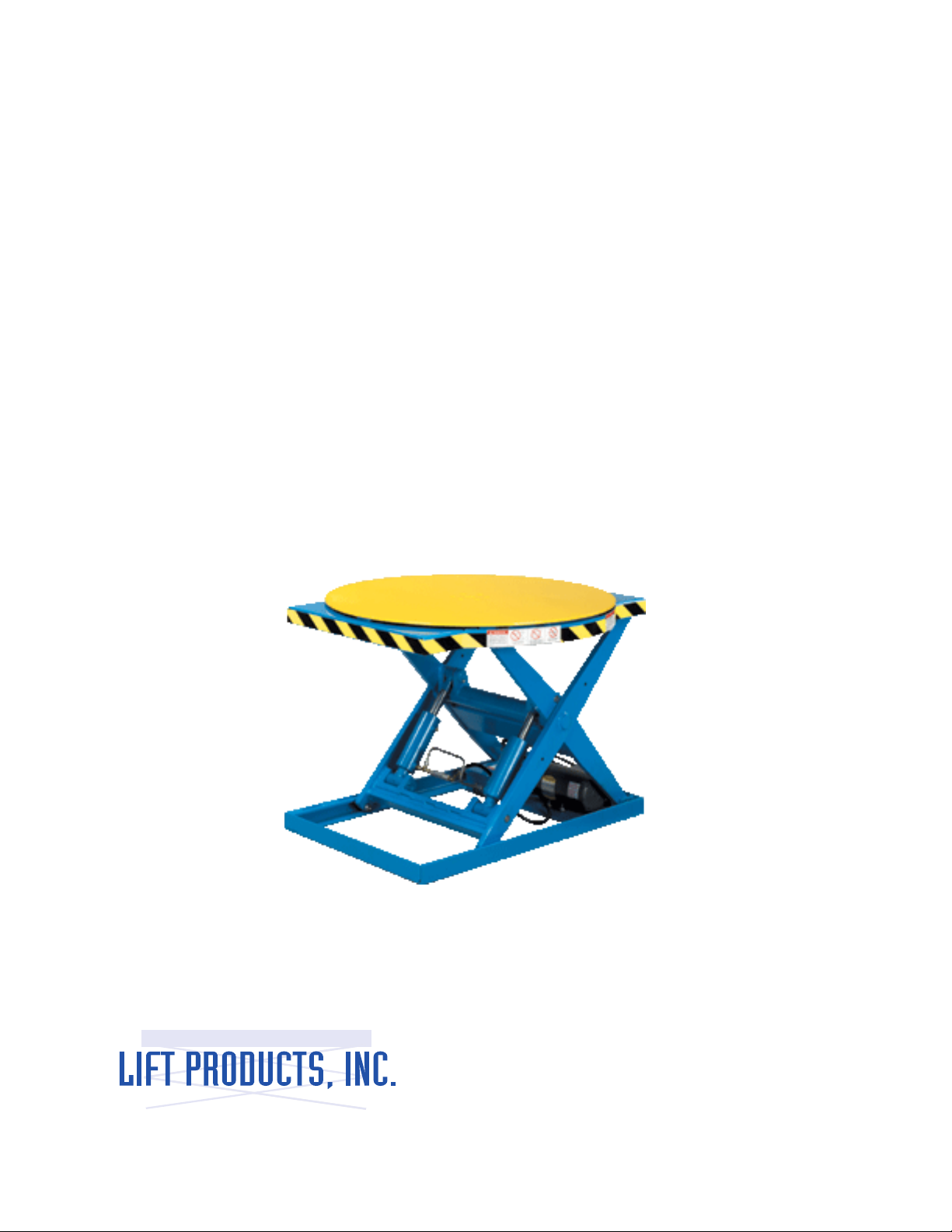
Roto-Max
Work Posioner
Operaon
Maintenance
Li Products Inc.
P.O Box 349
Elm Grove Wisconsin 53122-0349
PH: 877-543-8776 FX: 262-521-5725
Manual #19950
1

2
WARNING
Do not operated this li table unless you have been trained and authorized to do so and have
read all warnings and instrucons in operator’s manual and on the li table.
Do not operate this li table unl you have checked its condion. Give special aenon to
electrical system, li system (including limit switch), guards and safety devices.
Operate li table only from designed operang posion. Never place and part of your body into
the structure. Keep feet clear of li table.
Do not overload li table. Check capacity plate for load weight and loading informaon.
Before liing, be sure load is centered.
Do not handle unstable or loosely stacked loads. Use special care when handling long, high, or
wide loads.
Watch out for obstrucon, especially overhead.
Do not li personnel.
Do not allow anyone to place any part of their body into or under the liing mechanism.
When leaving li table, fully lower liing mechanism. When leaving li table unaended, also
disconnect power.

3
SECTION 1
DESCRIPTION
1-1 INTRODUCTION
This preliminary publicaon describes the Li Table Series manufactured by Li Products, Inc.
Elm Grove, Wisconsin 53122-0349. Included are operaon instrucons, planned maintenance
instrucons, lubricaon procedures, and a paral parts list with parts locaon illustraons.
For any maintenance instrucons not contained in this preliminary publicaon, contact Li
Products Customer Service. Be prepared to give model number, serial number, liing capacies
and li travel of your table.
The model number, serial number and liing capacies are stamped on the name plate
(Figure 1-1). The li travel can be determined by subtracng the lowered height from the el-
evated height.
Users shall comply with all requirements indicated in current edion of A.N.S.I MN29.1. By
following these requirements and the recommendaons contained in this manual, you will
receive many years of dependable service from your li table.
Figure 1-2 shows the locaon and idencaon of the decals. Also listed is the touch-up paint
as well as the locaon of the name plate. Figure 1-3 shows the locaons of the li table main
components.
Note: The user shall see that all name plates and markings are in place and are maintained in a
legible condion.

4
Serial No:
Model:
Liing Capacity:
Service Weight:
Edgeload Capacity:
Axel Load Capacity
1-2. GENERAL DESCRIPTION
The li tables have been designed primarily for indoor applicaons. All models are similar in
design but dier in capacity, li height and plaorm size.
The li and lower moon is controlled by a control box aached by a cord. The control box is
mounted on a magnet for easy aachment to a convenient locaon.
1-3 SAFETY FEATURES
The li tables are designed and engineered to provide maximum safety for operator and
payload. Some of the safety features incorporated into the design are:
• All control funcons automacally return to “OFF” when released.
• Travel limit switch to restrict li moon above the preset limit
• Pressure compensated ow control valve regulates maximum lowering speed within
prescribed limits
• Maintenance Safety Bars to support li table during maintenance operaons.
• High visibility color scheme of the li table provides visual alert of its presence
INSTALLATION
2-1. RECEIVING INSTRUCTIONS
Upon receipt, visually inspect the li table. If any damage is found, report it to the carrier and to
your Li Products dealer immediately.
Remove all packing and strapping material. Check the plaorm size type of electrical system,
ect., to be sure the li table is correct for the intended applicaon.

5
2-2. INSTALLATION INSTRUCTIONS
WARNING: Modicaon and addions which aect capacity and safe operaon shall not be
performed by the customer or user without manufacturers prior wrien approval.
1. Clean the installaon area.
CAUTION: The li table should only be picked up from under the base. Do not li the table by
the plaorm.
2. Posion the li table in the desired posion.
NOTE: The li table comes pre-wired with a 10 foot power cord. Check the decal located on the
electrical box for the voltage/phase and be sure you have the same power supply source. The
proper plug and mang receptacle must be purchased and installed by the user.
NOTE: Units equipped for a 115 volt power supply need to have a separate 20 amp rated circuit
and proper wiring to ensure an actual 115 volts at the li table electrical box when operang
under a full load.
3. Install the proper plug and connect to the power receptacle.
4. Using the control box, check for proper operaon. When the UP buon is depressed
the plaorm should remain staonary. When the DOWN buon is pressed the
plaorm should lower
5. Raise the plaorm and swivel both maintenance safety bars against the base. Lower
the plaorm unl the safety base contact the end of the base and the plaorm does
not lower any further.
6. Check for oil in the hydraulic reservoir. (note: Unit is supplied with oil).
7. The base contains pre-drilled mounng holes. Mark the locaon of these holes on the
oor.
8. Shi the li table over, drill holes in the oor and install anchors.
9. Reposion the li table and shim unl lever. Make sure the li table is fully supported
along its enre base with shims or concrete grout.
10. Bolt the base to the anchors installed in the oor.
11. Raise the plaorm and posion the maintenance safety bars in their proper
disengaged posion.
12. Operated the li table through several complete cycles and check for pinched hosed
or hydraulic leaks from ngs that may have loosened during shipping.

OPERATION
3-1. GENERAL
This secon gives detailed operang instrucons for the li table. Roune precauons are
included for safe operaon.
3-2. OPERATING PRECAUTIONS
WARNING: Improper operaon of the li table may result in operator injury or load and/or li
table damage. Observe the following precauons when operang the li table.
1. Do not operate this li table unless you have been trained and authorized to do so.
Read all warning and instrucons in this manual and on the li table.
2. Do not operate this li table unl you have checked its condion. Give special
aenon to electrical system, li system, guards and safety devices.
3. Do not exceed the rated capacity (see name plate). Overloading may result in
damage to the hydraulic system and structural components. Refer to paragraph 3-3.
4. Do not handle unstable or loosely stack loads. Use special care when handling long,
high, or wide loads to avoid pping, loss of load, or striking bystanders.
5. Check for obstrucons when raising or lowering the li table.
6. Operate li table only from design operang posion. Never place any part of your
body into the structure. Keep feet clear of li table.
7. Watch out for obstrucons overhead.
8. Do not li personnel.
9. Do not allow anyone to place any part of their body into or under the liing
mechanism.
10. When leaving li table, fully lower liing mechanism. When leaving li table
unaended, also disconnect power.
3-3. LOAD CAPACITY
The load capacity rang is stamped on the name plate. This load capacity assumes the load is
uniformly distributed and centered on the plaorm.
3-3.1. STATIC EDGE LOADS
The li table is designed for uniformly distributed centered loads. If the load is lied at the
sides or ends of the plaorm, the stac edge load stamped on the name plate should not be
exceeded.
6

6
3-3.2. AXLE (ROLLING EDGE) LOADS
When a load is rolled onto the plaorm, the li table should be fully lowered. The axle load
stamped on the name plate should not be exceeded.
3-4. BEFORE OPERATION
Table 3-1 covers important points on the li table which should be checked prior to operaon.
Depending on use, some li tables may require addional checks. When the li table is used on
a round-the clock basis, it should be examined aer each shi.
Figure 3-1 shows a sample format for a Operator Check List which can be modied as necessary
to t your operaon.
WARNING: Periodic maintenance of this li table by a QUALIFIED TECHNICIAN is required.
CAUTION: A QUALIFIED SERVICE TECHNICIAN should check the li table monthly for proper
lubricaon, proper uid levels, motor maintenance and other areas specied in Secon 4.
WARNING: If the li table is found to be unsafe and in need of repair, or contributes to an
unsafe condion, report it immediately to the designated authority. Do not operate it unl it
has been restored to a safe condion. Do not make any unauthorized repairs or adjustments.
All service must be performed by a qualied maintenance technician.
7

Table 3-1. Operator Check List
8
ITEM
• Decals&NamePlate
• Hardware
• HydraulicLines
• Lift&Lower
• LiftCylinders
• LiftLimitSwitch
• LiftMotor
• PivotPoints
• Platform
• Power&SwitchBoxCords
• PushButtons
• Rollers
• Drift
PROCEDURE
• Checkthatalldecalsandnameplateare
inplaceandlegible.
• Checkforsignsoflooseormissing
hardware.
• Checkforcutorfrayedhose,leaking
ttingsordamagedlines.
• Checkforproperoperationofliftand
lowertotheirmaximumpositions
• Checkforsignsofleakage
• Checkforlooseorbentmounting.Check
thatthelimitswitchshutsoffthepump
motoratthepresentplatformheight.
• Checkforgrindingorlaboringsounds
• Checkforsmoothpivotingaction
• Checkfordentsorwarpage
• Checkforcutorfrayedcord
• Checkthatthepushbuttonsdonotstick
ormalfunctionwhenpressed
• Checkupperandlowerrollersforsignof
wear
• Checkforexcessivedownwarddrift
whencontrolsareinneutralposition

8 9
3-5. OPERATION
3-5.1 TRAINING
Only operators trained to adhere strictly to the operang instrucons shall be permied to
operate the li table.
The user shall ensure that operators understand that safe operaon is the operator’s
responsibility. The user shall also ensure that operators are knowledgeable of and observe the
safety rules and pracces.
An eecve operator training program should center around company’s policies, operang
condions , and li tables, The program should be presented completely to all new operators
and not condensed for those claiming previous experience.
3-5.2 LOADING
1. Always center the load on the plaorm as much as possible. Refer to paragraph 3-3
for load capacity.
2. If the load is lied at the sides or ends of the plaorm, refer to paragraph 3-3.1 for
stac edge load capacity.
3. When a load is rolled onto the plaorm the li table should be fully lowered. Refer
to paragraph 3-3.2 for rolling edge load capacity.
3-5.3 RAISING
CAUTION: Do not exceed the rated frequency of operaon indicated on the li table.
Pressing and holding the UP push buon acvates the pump and motor causing the cylinder(s)
to extend and the plaorm to raise. If the table is overloaded, the relief valve should open,
prevenng buildup of excessive pressure. When the li table reaches a preset height the li
limit switch will cause the li table to stop. When the UP push buon is released the plaorm
with remain in posion.
CAUTION: Do not connue to press the UP push buon if the li table has reached the end
of its travel or is not raising. The pump and/or motor can be permanently damaged by doing
this.
3-5.4 LOWERING
Pressing and holding the DOWN push buon acvates the lower solenoid valve. Oil from the
cylinder is directed back to the reservoir, allowing the li table to lower at a controlled rate.
When the DOWN push buon is released, the plaorm will remain in posion.

10
Electric Li Table
Daily Operator Check-O List
Date
Truck No.
Dept
Operator
Model No.
Shi
CHECK
Decals & Name Plate
Condion of Hydraulic Lines
Condion of Power
& Switchbox Controls
Li Lower Controls
Li Limit Operaons
Missing Hardware
Hydraulic Leaks, Cylinders,
Valves, Hoses, Etc.
Pivot Points
Rollers
Li Motor
Plaorm
No Excessive Dri
OK NEEDMAINTENANCE
Table of contents
Popular Valve Positioner manuals by other brands


Parker
Parker MX80L series product manual

Westlock
Westlock Quantum 2800 Installation & operating instructions

Samson
Samson 3730-0 Mounting and operating instructions

Samson
Samson TROVIS 3730-3 Mounting and operating instructions

ESCO Technologies
ESCO Technologies ETS LINDGREN 2302-001 user manual

SMC Networks
SMC Networks IP8000 manual

Samson
Samson FOUNDATION 3730-5 Mounting and operating instructions

Samson
Samson TROVIS SAFE 3731-3 Mounting and operating instructions

Flowserve
Flowserve Logix 3400MD User instructions

halstrup-walcher
halstrup-walcher HIPERDRIVE instruction manual

ABB
ABB TZIDC Commissioning instructions

Samson
Samson FOUNDATION 3730-5 Mounting and operating instructions