Licht MFC-400/I-VAC User manual
Voltage Indicator/Transducer
models MFC-400/I-VAC and I-VDC
Technical Manual
Licht

Rev. A0 (20–05–09) MFC-400/I-VAC and I-VDC Technical Manual 1
Contents
1 Introduction 2
2 Front panel indication 3
3 Configuration 4
3.1 Parameter reset 4
4 Programmable parameters 5
4.1 General parameters 5
4.2 Current outputs (option) 5
4.3 MODBUS protocol 5
4.4 DNP3 protocol (option) 6
4.5 Language 7
A Specifications 8
B Connection diagrams 9
C MODBUS registers 13
Licht http://www.licht-labs.com
Rev. A0 (20–05–09) MFC-400/I-VAC and I-VDC Technical Manual 2
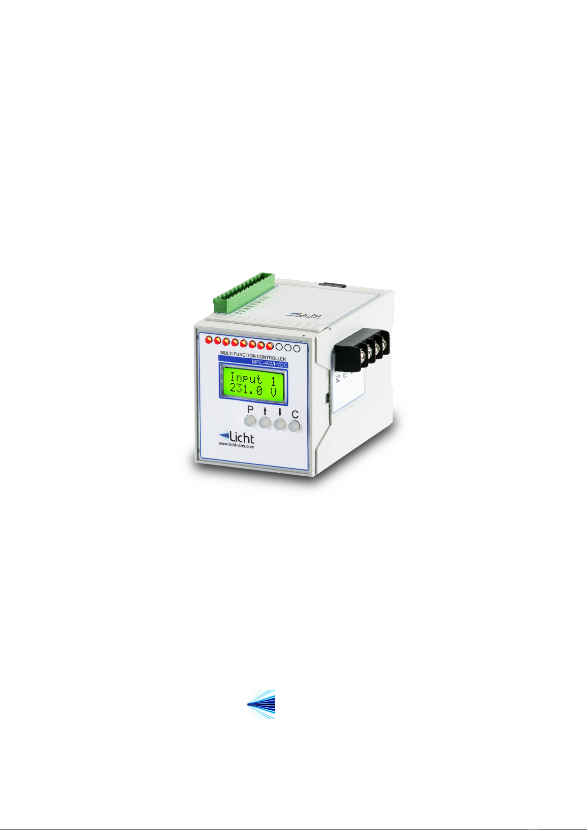
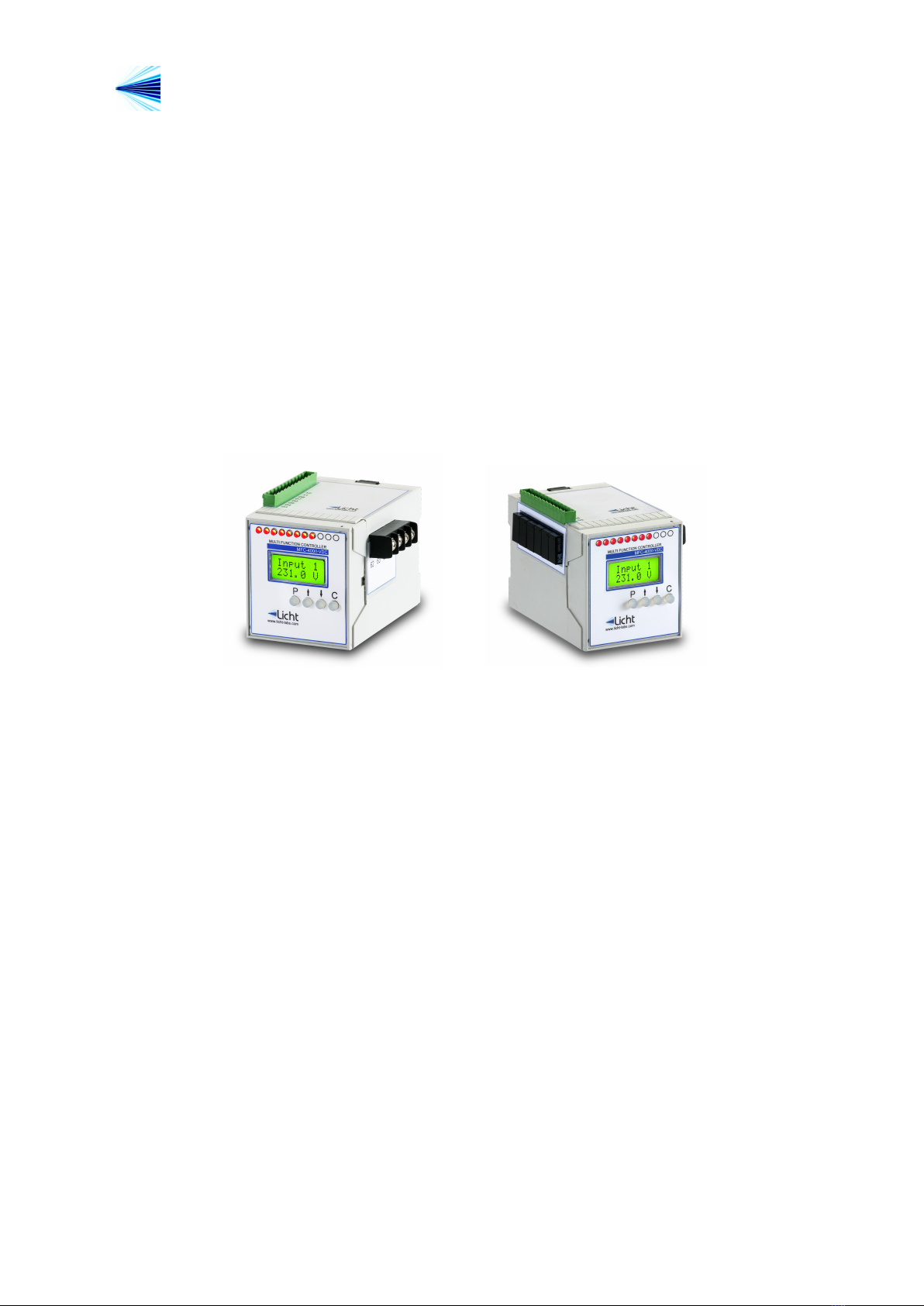
1 Introduction
The MFC-400/I-VAC and MFC-400/I-VDC are precise, highly reliable and versatile mi-
crocontrolled devices designed to read, display and retransmit AC or DC voltage values.
Each MFC-400/I-VAC or I-VDC features one isolated RS-485 port, which can be used
for communication using the MODBUS or DNP3 protocols.
All signals that enter and exit the indicator are galvanically isolated, preventing po-
tentially damaging noise and transients from being transferred between subcircuits or
retransmitted to other devices.
Figure 1.1 MFC-400/I-VDC Indicator
Licht http://www.licht-labs.com
Rev. A0 (20–05–09) MFC-400/I-VAC and I-VDC Technical Manual 3
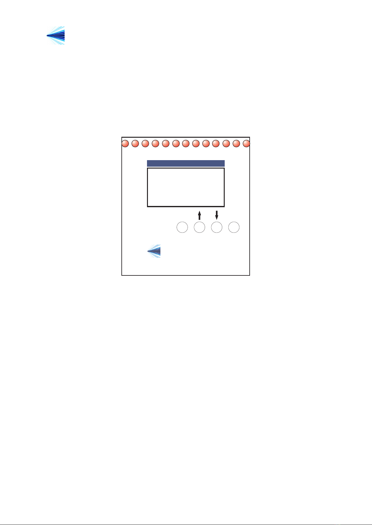
2 Front panel indication
During operation, the MFC-400/I-VAC or I-VDC displays its voltage measurement. The
presented value is equal to the measured voltage multiplied by the Sampling Factor para-
meter.
C
P
R1 R2 R3 R4 R5 R6 R7 R8 R9 R10 R11
MFC-400/I-VDC
MULTI FUNCTION CONTROLLER
Licht
www.licht-labs.com
R12 R13
Input 1
231.0 V
Figure 2.1 Front Panel

Licht http://www.licht-labs.com
Rev. A0 (20–05–09) MFC-400/I-VAC and I-VDC Technical Manual 4
3 Configuration
Parameterization
The MFC-400/I-VAC and MFC-400/I-VDC feature 4 keys to access their functions. The
procedure to configure any parameter is as follows:
1. Press the Pkey to enter the parameters menu.
2. Enter the currently configured 4 letter password one letter at a time, using the ↑
and ↓keys to select each letter and Pto advance between letters. The default
password is AAAA.
3. Using the ↑and ↓keys, choose the desired parameter.
4. Press Pto confirm the parameter’s selection.
5. Choose the desired value with the ↑and ↓keys.
6. Confirm pressing P.
By holding down the ↑or ↓keys it is possible to advance through the options faster.
The configuration sequence can be cancelled at any time by pressing C.
3.1 Parameter reset
This device can be reset to factory settings. This procedure also resets its password to
AAAA. To do so, power up the device while pressing C.

Licht http://www.licht-labs.com
Rev. A0 (20–05–09) MFC-400/I-VAC and I-VDC Technical Manual 5
4 Programmable parameters
The MFC-400/I-VAC and MFC-400/I-VDC were developed to provide the user with the
greatest possible flexiblity, such that all supervision and configuration can be executed
on-site or remotely through the existing communication channels.
We define all user-configurable parameters below.
4.1 General parameters
Parameter:Sampling Factor
Options: 1 to 1000.
Description: ratio between the voltage displayed by the MFC-400 and the sampled
voltage.
Parameter:AC frequency
Options: 60 Hz, 50 Hz.
Description: input voltage frequency (only applicable to the MFC-400/I-VAC).
4.2 Current outputs (option)
Parameter:Output Scale
Options: 0-1, 0-5, 0-10, 0-20, 4-20 mA
Description: refers to the various configurable current loop scales.
Parameter:Full Scale
Options: 1 to 1000 V, in increments of 1 V.
Description: input voltage corresponding to the current loop’s full scale output. For
example, if Full Scale = 100 V and Output Scale = 4-20 mA, the current loop output will
be 4 mA for a 0 V input and 20 mA for a 100 V input.
4.3 MODBUS protocol
Parameter:Baud Rate
Options: 9600, 19200, 38400, 57600, 115200 bps.
Description: baud rate for the RS-485 link.

Licht http://www.licht-labs.com
Rev. A0 (20–05–09) MFC-400/I-VAC and I-VDC Technical Manual 6
Parameter:Format
Options: 8N1, 8E1, 8O1, 8N2.
Description: symbol transmission format, where:
◦8N1: 8 data bits, no parity, 1 stop bit.
◦8E1: 8 data bits, even parity, 1 stop bit.
◦8O1: 8 data bits, odd parity, 1 stop bit.
◦8N2: 8 data bits, no parity, 2 stop bits.
Parameter:Address
Options: 1 to 247.
Description: MODBUS address for the MFC-400.
4.4 DNP3 protocol (option)
Parameter:Baud Rate
Options: 9600, 19200, 38400, 57600, 115200 bps.
Description: baud rate for the RS-485 link.
Parameter:Format
Options: 8N1, 8E1, 8O1, 8N2.
Description: symbol transmission format, where:
◦8N1: 8 data bits, no parity, 1 stop bit.
◦8E1: 8 data bits, even parity, 1 stop bit.
◦8O1: 8 data bits, odd parity, 1 stop bit.
◦8N2: 8 data bits, no parity, 2 stop bits.
Parameter:Address
Options: 0x0000 to 0xFFEF.
Description: DNP3 outstation address in hexadecimal notation.
Parameter:Application Layer Confirmation
Options: Only when transmitting events or multi-fragment responses, Always.
Description: Selects when the MFC-400 outstation should request application layer
confirmations.
Parameter:Maximum Inter-Octet Gap
Options: 2 to 100 ms.

Licht http://www.licht-labs.com
Rev. A0 (20–05–09) MFC-400/I-VAC and I-VDC Technical Manual 7
Description: The DNP3 specification states that frames should not have inter-octet
gaps. In accordance, the MFC-400 never inserts inter-octet gaps when transmitting data.
However, we allow the option to tolerate gaps in incoming transmissions. Frames featuring
inter-octet gaps larger than the Maximum Inter-Octet Gap will be quietly dropped.
Parameter:Backoff Delay (Fixed)
Options: 1 to 100 ms.
Description: See description for Backoff Delay (Random).
Parameter:Backoff Delay (Random)
Options: 1 to 100 ms.
Description: The MFC-400 is designed for multi-drop scenarios where more than one
outstation may transmit over the same line. To handle collision avoidance, a backoff
scheme is implemented. Before transmitting, the MFC-400 always waits for the line to
become idle. Once that happens, it waits for Tdelay =Tf ixed +Trandom ms, where Tf ixed
is the fixed backoff delay and Trandom is a random value, uniformly distributed between 0
and the random backoff delay parameter. If after Tdelay ms the line is still idle, then the
MFC-400 begins transmission.
Parameter:Insert Inter-frame Gap
Options: Never, Always.
Description: The DNP3 specification states that no inter-frame gaps are required. How-
ever, some masters have been observed to drop frames when no inter-frame gaps are pro-
vided. This option allows communicating with such non-compliant devices. We discourage
its use, given that the forced inter-frame gap implies a forced backoff-delay.
4.5 Language
Parameter:Language
Options: Portuguese (PT_BR), English (EN_US).
Description: Language of the messages and menus displayed on the MFC-400’s front
panel.

Licht http://www.licht-labs.com
Rev. A0 (20–05–09) MFC-400/I-VAC and I-VDC Technical Manual 8
A Specifications
Power Supply Isolated, 80-260 Vac/Vdc.
Power Consumption < 8 W
Operating Temperature -20 to 70 ◦C(LCD display)
-40 to 85 ◦C(VFD display)
Enclosure Rating IP20
Mounting Options 35 mm DIN rail
Dimensions 70 x 75 x 100 mm
Weight 500 g
DC Input Scale: specifiable
Error/Non-linearity: 0.2% + 0.1% /10 ◦C
AC Input Scale: specifiable
Error/Non-linearity: 0.5% + 0.1% /10 ◦C
Current Outputs Scales: 0-1, 0-5, 0-10, 0-20, 4-20 mA
Error/Non-linearity: 0.2% + 0.1% /10 ◦C
Galvanic Isolation
(60 Hz, 1 min.)
DC Input 1.5 kV
AC Input 1.5 kV
Outputs 1.5 kV
Communication 1.5 kV
Communication RS-485 - MODBUS RTU or DNP3
9600, 19200, 38400, 57600, 115200 bps
8N1, 8E1, 8O1, 8N2
Displays 2 lines with 16 characters each (5 mm).
LCD with backlight or VFD.
Licht http://www.licht-labs.com
Rev. A0 (20–05–09) MFC-400/I-VAC and I-VDC Technical Manual 9
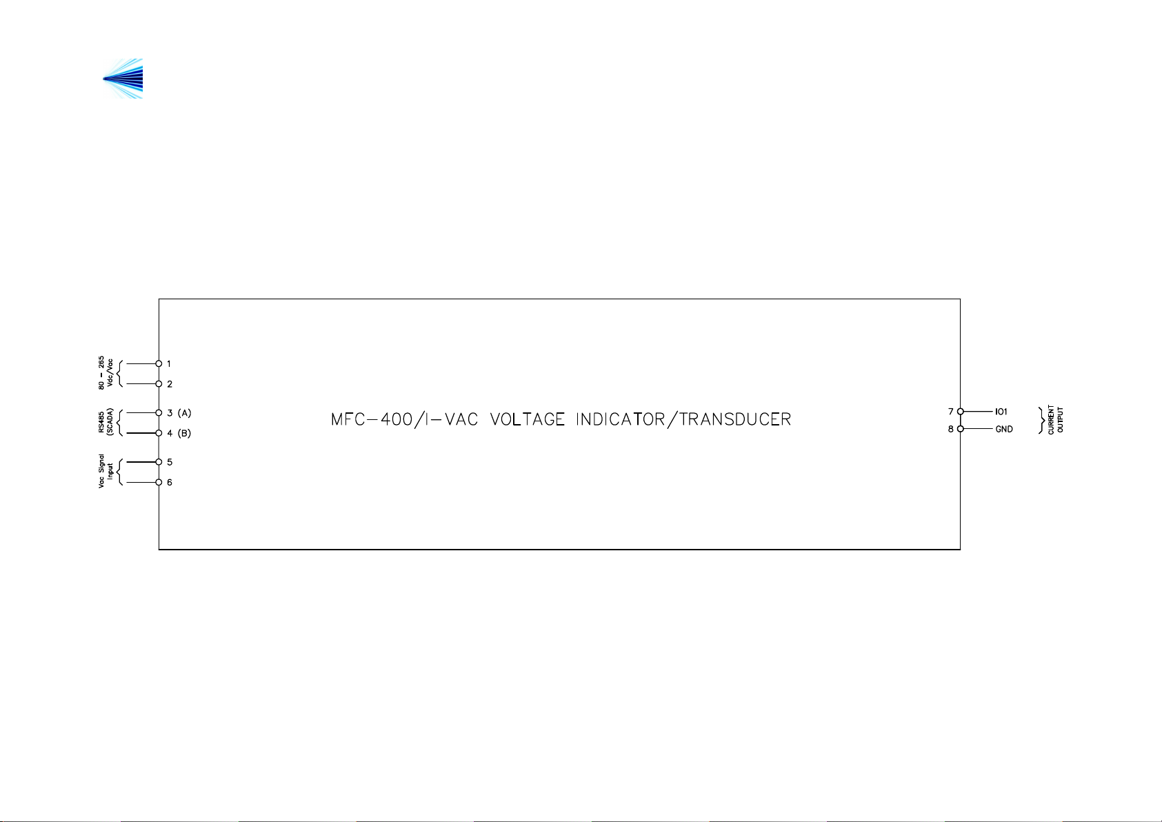
B Connection diagrams
This manual suits for next models
1
Table of contents
Other Licht Transducer manuals


Popular Transducer manuals by other brands


Mianyang Weibo Electronic
Mianyang Weibo Electronic WB Series user manual

ProMinent
ProMinent Dulcometer DMT operating instructions

MKS
MKS MicroPirani 925 Series Short form manual

WIKA
WIKA WU-20 operating instructions

Alcatel Vacuum Technology
Alcatel Vacuum Technology BARATRON 622A instruction manual

Camille Bauer
Camille Bauer SIRAX CH-5610 operating instructions


