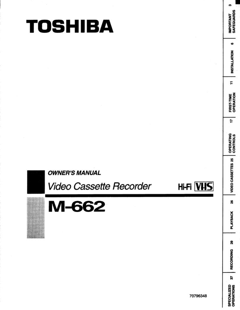
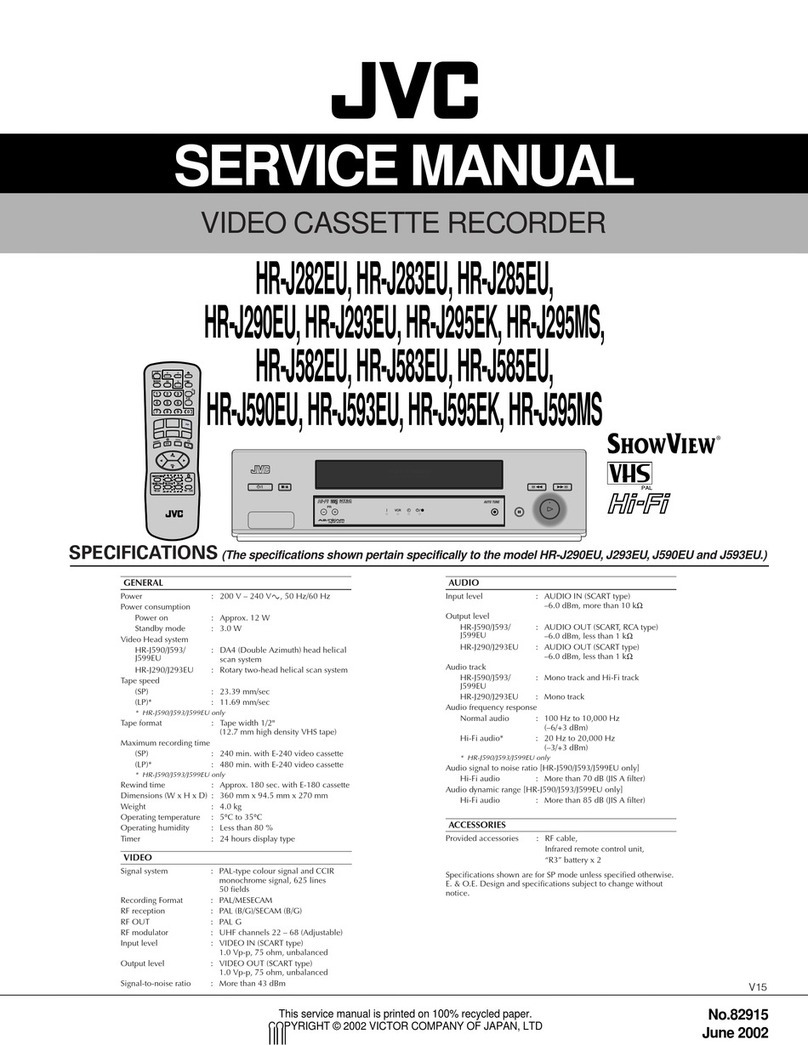
LG EC290W User manual

SERVICE MANUAL
VIDEO CASSETTE
RECORDER
SERVICE MANUAL
MODELS : EC290W/EC290SW/EC470W/
EC490SW/EC970W/EC990SW
CAUTION
BEFORE SERVICING THE UNIT, READ THE “SAFETY PRECAUTIONS”
IN THIS MANUAL.
EC470W/970W EC290W/290SW/490SW/990SW
MODELS : EC290W/EC290SW/EC470W/EC490SW/EC970W/EC990SWSERVICE MANUAL

TABLE OF CONTENTS
SECTION 1
SUMMARY
KEY TO ABBREVIATIONS . . . . . . . . . . . . . . . . 1-1
IMPORTANT SAFETY PRECAUTIONS
. . . . . . . . . . 1-2
• Precautions During Servicing
SAFETY CHECK AFTER SERVICING . . . . . . . . 1-3
• Insulation resistance test
• Dielectric strength test
• Clearance distance
• Leakage current test
PROPOSAL FOR APPLYING SHORT
PROTECTION . . . . . . . . . . . . . . . . . . . . . . . . . . .1-4
SERVICE NOTICE ON REPLACING EEPROM . .1-5
SERVICE INFORMATION FOR EEPROM
IC SETTING . . . . . . . . . . . . . . . . . . . . . . . . . . . .1-6
SPECIFICATIONS . . . . . . . . . . . . . . . . . . . . . . . 1-7
SECTION 2
CABINET & MAIN CHASSIS
SERVICE METHOD . . . . . . . . . . . . . . . . . . . . . 2-1
Electrical Part . . . . . . . . . . . . . . . . . . . . . . . . . . . . . 2-1
EXPLODED VIEWS . . . . . . . . . . . . . . . . . . . . . . 2-2
1. Cabinet & Main Frame Section . . . . . . . . . . . . . 2-2
2. Packing & Accessory Section . . . . . . . . . . . . . . 2-3
SECTION 3
ELECTRICAL
ELECTRICAL ADJUSTMENT POINTS
ARRANGEMENT . . . . . . . . . . . . . . . . . . . . . . . .3-1
ELECTRICAL ADJUSTMENT PROCEDURES . . 3-2
1. Servo Circuit . . . . . . . . . . . . . . . . . . . . . . . . . . . 3-2
ELECTRICAL TROUBLESHOOTING GUIDE . . . 3-4
1. Power Circuit(SMPS) . . . . . . . . . . . . . . . . . . . . . 3-4
2. Servo Circuit . . . . . . . . . . . . . . . . . . . . . . . . . . .3-7
3. System & Front Panel Circuit . . . . . . . . . . . . . . .3-10
4. Y/C Circuit . . . . . . . . . . . . . . . . . . . . . . . . . . . . .3-13
5. Tuner/IF Circuit . . . . . . . . . . . . . . . . . . . . . . . . .3-17
6. Hi-Fi Circuit . . . . . . . . . . . . . . . . . . . . . . . . . . . .3-20
BLOCK DIAGRAMS . . . . . . . . . . . . . . . . . . . . .3-22
1. Power Block Diagram . . . . . . . . . . . . . . . . . . . .3-22
2. Tuner/IF, NICAM & A2 Block Diagram . . . . . . . .3-24
3. Y/C Block Diagram . . . . . . . . . . . . . . . . . . . . . .3-26
4. Hi-Fi Block Diagram . . . . . . . . . . . . . . . . . . . . .3-27
5. System Block Diagram . . . . . . . . . . . . . . . . . . .3-28
CIRCUIT DIAGRAMS . . . . . . . . . . . . . . . . . . . .3-30
1. Power Circuit Diagram . . . . . . . . . . . . . . . . . . . .3-30
2. Tuner, NICAM, A2 Circuit Diagram . . . . . . . . . . .3-32
3. A/V Circuit Diagram . . . . . . . . . . . . . . . . . . . . . .3-34
4. System Circuit Diagram . . . . . . . . . . . . . . . . . . .3-36
5. Hi-Fi Circuit Diagram . . . . . . . . . . . . . . . . . . . . .3-38
• WAVEFORM . . . . . . . . . . . . . . . . . . . . . . . . . . . .3-40
• CIRCUIT VOLTAGE CHART . . . . . . . . . . . . . . . .3-42
PRINTED CIRCUIT BOARD DIAGRAMS . . . . .3-46
1. MAIN P.C.Board . . . . . . . . . . . . . . . . . . . . . . . .3-46
2. KEY (LEFT) P.C.Board . . . . . . . . . . . . . . . . . . .3-48
SECTION 4
MECHANISM
SECTION 5
REPLACEMENT PARTS LIST
• Mechanical Section . . . . . . . . . . . . . . . . . . . . . . . .5-1
• Electrical Section . . . . . . . . . . . . . . . . . . . . . . . . .5-3
NOTE) The table of contents for this section is edited
NOTE) separately.

1-1
A AC :Alternating Current
ACC :Automatic Color Control
ACSS :Automatic Channel Setting System
ADJ :Adjust
A/E :Audio Erase
AFC :Automatic Frequency Control
AFT :Automatic Fine Tuning
AGC :Automatic Gain Control
A.H.SW :Audio Head Switch
ALC :Automatic Level Control
AM :Amplitude Modulation
AMP :Amplifier
ANT :Antenna
APC :Automatic Phase Control
ASS’Y :Assembly
AUX :Auxiliary
B B :Base
BGP :Burst Gate Pulse
BPF :Bandpass Filter
BS :Brodcasting Satellite
BW or B/W :Black and White
C C :Capacitor, Chroma, Collector
CAN :Cancel
CAP :Capstan
CAP.BRK :Capstan Brake
CAP.RVS :Capstan Reverse
CATV :Cable Television
CBA :Circuit Board Assembly
CCD :Charge Coupled Device
C.CTL :Chro Control, Capstan Control
CFG :Capstan Frequency Generator
CHROMA :Chrominance
CNR :Chroma Noise Redution
COMB :Combination
Comb Filter
COMP :Comparator
Composite
Compensation
CONV :Converter
C.ROT SW :Color Rotary Switch
CS :Chip Selcet
C.SYNC :Composite Synchronization
CTL DIV :Control Divide
CUR :Current
CYL :Cylinder
D D :Drum, Digital, Diode, Drain
D.ADJ :Drum Adjust
DC :Direct Current
D.CTL :Drum Control
DEMOD :Demodulator
DET :Detector
DEV :Deviation
DHP :Double High Pass
DIGITRON :Digital Display Tube
DL :Delay line
DOC :Drop Out Compensator
DUB :Dubbing
D.V SYNC :Dummy Vertical Synchronization
E E :Emitter
EE :Electric to Eletric
EMPH :Emphasis
ENA :Enable
ENV :Envelope
EP :Extended Play
EQ :Equalizer
EXP :Expander
F F :Fuse
FB :Feed Back
FBC :Feed Back Clamp
FE :Full Erase
FG :Frequency Generator
FL :Filter
FM :Frequency Modulation
F/R :Front/Rear
FS :Frequency Synthesizer
FSC :Subcarrier Frequency
F/V :Frequency Voltage
G GEN :Generator
H H :High, Horizontal
I IC :Integrated Circuit
IF :Intermediate Frequency
INS :Insert
L L :Low, Left, Coil
LD :LED
LD VTG CTL
:Loading Voltage Control
LECHA :Letter Character
L.M :Level Meter
LP :Long Play
LPF :Low Pass Filter
M MAX :Maximum
MD :Modulator
MECHA.CTL
:Mechanism Control
MIC :Microphone
MIN :Minimum
MIX :Mixer, Mixing
M.M. :Monostable, Multivibrator
MMV :Mono Multi Vibrator
MOD :Modulation, Modulator
MODEM :Modulator-Demodulator
MPX :Multiplex
N NR :Noise Reduction
O OSC :Oscillator
OSD :On Screen Display
P PB :Playback
PCB :Printed Circuit Board
P.CTL :Power Control
PRE-AMP :Preamplifier
P.F :Power Failure
PG :Pulse Generator
PLL :Phase Locked Loop
PREM.DET :Premire Detect
P.P :Peak-to-Peak
PS :Phase Shift
PWM :Pulse Width Modulation
PWR CTL :Power Control
Q Q :Transistor
QH :Quasi Horizontal
QSR :Quick Setting Record
QTR :Quick Timer Record
QV :Quasi Vertical
R R :Resistor, Right
RE(or RC) :Remocon, Receiver
REC :Recording
REC S ‘H’ :Record Start ‘Hight’
REF :Reference
REG :Regulated, Regulator
REMOCON :Remote Control(unit)
RF :Radio Frequency
R/P :Record/Playback
RTC :Reel Time Counter
S S :Serial
S.ACCEL :Slow Accel
SAOP :Second Audio Program
SC :Scart, Simulcast
S.DET :Secam Detect
SH :Shift
SHARP :Sharpness
SIF :Sound Intermediate Frequency
SLD :Side Locking
S/N :Signal to Noise Ratio
SP :Standard Play
ST :Stereo
SUB :Subtract, Subcarrier
SW or S/W :Switch
SYNC :Synchronization
SYSCON :System Control
T T :Coil
TP :Test Point
TR :Transistor
TRK :Tracking
TRANS :Transformer
TU :Tuner, Take-up
U UHF :Ultra High Frequency
UNREG :Unregulated
V V :Volt, Vertical
VA :Always Voltage
VCO :Voltage Controlled Oscillator
VGC :Voltage Gain Control
VHF :Very High Frequency
V.H.SW :Video Head Switch
VISS :VHS Index Search
VPS :Video Program System
VR :Variable Resistor or Volume
V-SYNC :Vertical Synchronization
VTG :Voltage
VV :Voltage to Voltage
VXO :Voltage X-tal Oscillator
W W :Watt
WHT :White
W/O :With out
X X-TAL :Crystal
Y Y/C :Luminance/Chrominance
YNR :Luminance Noise Reduction
Z ZD :Zener Diode
SECTION1 SUMMARY
KEY TO ABBREVIATIONS

1-2
Prior to shipment from the factory, the products are strictly inspected to conform with the recognized product
safety and electrical codes of the countries in which they are to be sold. However, in order to maintain such com-
pliance, it is equally important to implement the following precautions when a set is being serviced.
• Precautions during Servicing
1. Locations requiring special caution are denoted by labels and inscriptions on the cabinet, chassis and
certain parts of the product. When performing service, be sure to read and comply with these and other
cautionary notices appearing in the operation and service manuals.
2. Parts identified by the symbol and shaded (
Y
) parts are critical for safety.
Replace only with specified part numbers.
Note : Parts in this category also include those specified to comply with X-ray emission standards for
products using cathode ray tubes and those specified for compliance with various regulations
regarding spurious radiation emission.
3. Use Specified internal wiring. Note especially:
1) Double insulated wires
2) High voltage leads
4. Use specified insulating materials for hazardous live parts. Note especially:
1) Insulation Tape
2) PVC tubing
3) Spacers
4) Insulation sheets for transistor
5. Observe that wires do not contact heat producing
parts (heatsinks, oxide metal film resistors, fusible
resistors, etc.)
6. Check that replaced wires do not contact sharp edged
or pointed parts.
7. 1) When a power cord has been replaced, check
that A mark is made on the cord, under strain,
near the aperture, and the flexible cord is
subjected 100 times to a pull of 40N for a duration
of 1 second each.
2) During the test, the cord shall not be displaced by
more than 2mm
8. Also check areas surrounding repaired locations.
9. The internal wiring is secured so as not to approach the heating parts and high voltage parts by its shape.
So, these wires must be restored to its former state.
IMPORTANT SAFETY PRECAUTIONS
Fig. 1
Power Code
or Power Cord

1-3
Fig. 3
SAFETY CHECK AFTER SERVICING
Examine the area surrounding the repaired location for damage or deterioration. Observe that screws, parts and
wires have been returned to original positions. Afterwards, perform the following tests and confirm the specified
values in order to verify compliance with safety standards.
• Insulation resistance test
confirm the specified insulation resistance or greater between power cord plug prongs and externally exposed
parts of the set (RF terminals, antenna terminals, video and audio input and output terminals, incrophone jacks,
earphone jacks, etc.) See table below.
• Dielectric strength test
Confirm specified dielectric strength or greater between power cord prongs and exposed accessible parts of
the set (RF terminals, antenna terminals, video and
audio input and output terminals, incrophone jacks,
earphone jacks, etc.) See table below.
• Clearance distance
When replacing primary circuit components, confirm
specified clearance distance (d), (d') between sol-
dered terminals, and between terminals and sur-
rounding metallic parts. See table below.
Table 1 : Ratings for selected areas
* Class II model only.
Note. This table is unofficial and for reference only. Be sure to confirm the precise values for your particular
country and locality.
• Leakage Current test
Confirm specified or lower leakage current between B(earth ground, power cord plug prongs) and externally
exposed accessible parts (RF terminals, antenna terminals, video and audio input and output terminals, micro-
phone jacks, earphone jacks, etc.)
Measuring Method: (Power ON)
Insert load Z between B(earth ground, power cord
plug prongs) and exposed accessible parts. Use an
AC voltmeter to measure across both terminals of
load Z. See figure and following table.
Table 2:Leakage current ratings for selected areas.
Note. This table is for IEC member only. Be sure to confirm the precise values for your particular country and
Note. locality.
Chassis
d
a
Primary circuit terminals
Exposed
accessible
part Z
Load AC Voltmeter
Earth Ground,
Power cord plug prongs
B
Fig. 2
AC Line Voltage
AC Line Voltage
100 to 130 V
200 to 240 V
*100 to 130 V
*200 to 240 V
Europe
Australia
Europe
Australia
Other terminals
Antenna earth
terminals
i E0.7m A peak
i E2m A DC
i E0.7m A peak
i E2m A DC
F10 MΩ/500 V DC 4kV 1 minute
F6mm(d)
F8mm(d)
(a Power cord)
Region Load Z Leakage Current(i) Earth Ground
(B) to :
Region Insulation
Resistance
Dielectric
Strength Clearance
Distance(d),(d)
2kΩ
50kΩ

1-4
• The Contents of Examination
As all the IC that is applied to VCR is controlled by IIC, mutual communication, if Vcc of IC is short or open
with detecting ‘Acknowledge’data of the specific IC according to each power(5V, 5VT) µ-COM gets unable to
detect ‘ACK’data.
µ-COM regards this case as abnormal one and if it can’t detect ‘ACK’data for a certain time(3.5 sec) the sig-
nal of ‘Power Control’and ‘Timer Control’are switched to ‘Low’. As a result POWER Switching TR is kept from
generating heat and fire.
• POWER for each IC
S/ 5V POWER SECAM IC
Series 5VT POWER AVCP IC
P/Y/I 5V POWER Modulator
Series 5VT POWER AVCP IC
*Short protection off mode : DJ01 Diode in
PROPOSAL FOR APPLYING SHORT PROTECTION
IIC BUS
5VT SW POWER
CONTROL
MASTER
TIMER
CONTROL
5VT SW
SLAVE with 5V
SLAVE with 5V
5.3VA
Timer Control
AVCP IC
TUNER
Conception
BLOCK Diagram
5.2V 5.2VT
•IC to detect ‘ACK’data is selected as below because IC is different in accordance to region and option
5.3VA
Power Control
Modulator
Hi-Fi IC
NICAM IC
SECAM IC

1-5
In case that defective EEPROM of PAL models is replaced, to operate these sets from the initial state MP KEY
must be repaired as well before delivering to the customer.
If MP KEY isn’t repaired the setting of RF OUT channel or LANGUAGE might be different from that for cus-
tormer’s country.
•MP KEY : In case of PAL VCR if holding the REC button on the front panel and the CLEAR button on the
remote control handset for 5 ~ 7 seconds with power being switch all and no tapes,
OK is displayed at FLD for FLD models and LED becomes on for LED CLOCK models.
This is the state that initializing EEPROM is finished.
(In case of PAL VCP if holding the REC button on the front panel and the MENU button on the
remote control handset for 5 ~ 7 seconds with power being off and no tapes, All the LED DOTs
become on. This is the state that initializing EEPROM is finished.)
•MP KEY's function : MP KEY sets EEPROM's data up to the initial state.
SERVICE NOTICE ON REPLACING EEPROM
TIMER
AM
REC
VCR
OK
•FLD MODEL:
MP KEY “OK”
•LED CLOCK MODEL:
MP KEY Switch all on a Light
•LED DOT MODEL:
MP KEY Switch all on a Light

1-7
SPECIFICATIONS
General
Power : 100~240V, 50/60Hz
Power consumption : Approx. 12 watts(Energy Saving mode : 3 watts)
Video Head system : Rotary 2heads, helical scanning system
(2HD Model Only)
Double azimuth 4 heads, helical scanning system
(4HD MONO, 4HD Hi-Fi Model Only)
Tape speed : 23.39 mm/sec (SP mode)11.69 mm/sec(LP mode)
Tape format : Tape width 1/2”(12.7 mm high density VHS tape)
Maximum recording time : 4 hours in SP mode/8 hours in LP mode (with E-240 tape)
Rewind time : Approx. 150 sec. (with E-180 tape)
Dimensions (W X H X D) : 360 x 94.5 x 230 mm
Weight : 9.0 lbs. (4.0 kg)
Operating temperature : 41°F-95°F (5°C-35°C)
Operating humidity : Less than 80%
Timer : 24 hours display type
Video
Input level : VIDEO IN (RCA type)
1.0 Vp-p, 75 ohm, unbalanced
Output level : VIDEO OUT (RCA type)
1.0 Vp-p, 75 ohm, unbalanced
Signal to noise ratio : More than 43 dBm
RF Modulator : UHF 28~68(Adjustable)
Audio
Input level : AUDIO IN (RCA type)
-6.0dBm, more than 47kΩ
Output level : AUDIO OUT (RCA type)
-6.0 dBm, less than 1kΩ
Track Mono track & Hi-Fi track
Frequency response : Normal : 100 Hz - 10 kHz(-6/+3 dB)
Hi-Fi : 20 Hz - 20 kHz(3-/+3 dB)
Signal to noise ratio : Normal : More than 43 dBm(at SP mode)
Dynamic range : Hi-Fi : More than 70 dBm(at SP mode)
Hi-Fi : More than 85 dBm(at SP mode)
•Design and specifications are subject to change without notice.
:Hi-Fi Model only

2-1
SECTION2 CABINET & MAIN FRAME
Fig.2-1
SERVICE METHOD
(1) Disassembly Flow
(Positioned Upside Down)
(2) Re-assembly Flow for service like Fig. 2-1
(3) To check and replace Electrical parts
1Disassemble the unit according to
No.1) Disassembly Flow.
2Re-assemble the unit according to
No.2) Re-assembly Flow.
3Place the unit like Fig. 2-1
4 Check and replace Electrical parts.
NOTE :
1Insert Video Cassette Tape inversely like Fig. 2-1
to check and replace defective parts.
2In disassembling and reassembling, be careful not
to damaged CST switch.
Top Case
Bottom Cover
Front Panel
Housing & Deck
Assembly
Main C.B.A
LED C.B.A
LED C.B.A
Main C.B.A
Housing & Deck
Assembly
Housing y Mecanismo
Cassette Tape
(Upside Down)
C.B.A Princioal

2-2
EXPLODED VIEWS
1. Cabinet and Main Frame Section
283
280
284
261
260
457
A00
464
462
462
250
300
A43
330
452
457
320
A46
A42
A49
A
5
4
3
2
1
BCD
NOTE) Refer to “SECTION 5 REPLACEMENT
PARTS LIST”in order to look for the
part number of each part.
_ OPTIONAL PARTS
This manual suits for next models
5
Table of contents
Other LG VCR System manuals