LG SJ3 User manual

SERVICE MANUAL
CAUTION
BEFORE SERVICING THE UNIT, READ THE “SAFETY PRECAUTIONS”
IN THIS MANUAL.
SERVICE MANUAL
Internal Use Only
JANUARY, 2017P/NO : AFN77558553
MODEL:
SJ3
(SJ3, SPJ4B-W)
MODEL: SJ3 (SJ3, SPJ4B-W)
2.1 ch Wireless Sound Bar

1-1
CONTENTS
SECTION 1 ........ GENERAL
SECTION 2 ........ CABINET & MAIN CHASSIS
SECTION 3 ........ ELECTRICAL
SECTION 4 ........ WIRELESS SUBWOOFER PART

1-2
SECTION 1
GENERAL
CONTENTS
ESD PRECAUTIONS......................................................................................................................................... 1-3
WIRELESS SUBWOOFER CONNECTION....................................................................................................... 1-4
HIDDEN KEY MODE ......................................................................................................................................... 1-5
ESS / EQ PROGRAM UPDATE GUIDE............................................................................................................ 1-6
SPECIFICATIONS ............................................................................................................................................. 1-7
1-3
ESD PRECAUTIONS
Electrostatically Sensitive Devices (ESD)
Some semiconductor (solid state) devices can be damaged easily by static electricity. Such components
commonly are called Electrostatically Sensitive Devices (ESD). Examples of typical ESD devices are integrated
circuits and some field-effect transistors and semiconductor chip components. The following techniques should
be used to help reduce the incidence of component damage caused by static electricity.
1. Immediately before handling any semiconductor component or semiconductor-equipped assembly, drain off
any electrostatic charge on your body by touching a known earth ground. Alternatively, obtain and wear a
commercially available discharging wrist strap device, which should be removed for potential shock reasons
prior to applying power to the unit under test.
2. After removing an electrical assembly equipped with ESD devices, place the assembly on a conductive surface
such as aluminum foil, to prevent electrostatic charge buildup or exposure of the assembly.
3. Use only a grounded-tip soldering iron to solder or unsolder ESD devices.
4. Use only an anti-static solder removal device. Some solder removal devices not classified as "anti-static" can
generate electrical charges sufficient to damage ESD devices.
5. Do not use freon-propelled chemicals. These can generate electrical charges sufficient to damage ESD
devices.
6. Do not remove a replacement ESD device from its protective package until immediately before you are
ready to install it. (Most replacement ESD devices are packaged with leads electrically shorted together by
conductive foam, aluminum foil or comparable conductive materials).
7. Immediately before removing the protective material from the leads of a replacement ESD device, touch the
protective material to the chassis or circuit assembly into which the device will by installed.
CAUTION : BE SURE NO POWER IS APPLIED TO THE CHASSIS OR CIRCUIT, AND OBSERVE ALL OTHER
SAFETY PRECAUTIONS.
8. Minimize bodily motions when handing unpackaged replacement ESD devices. (Otherwise harmless motion
such as the brushing together of your clothes fabric or the lifting of your foot from a carpeted floor can generate
static electricity sufficient to damage an ESD device).
CAUTION. GRAPHIC SYMBOLS
THE LIGHTNING FLASH WITH APROWHEAD SYMBOL. WITHIN AN EQUILATERAL TRIANGLE, IS
INTENDED TO ALERT THE SERVICE PERSONNEL TO THE PRESENCE OF UNINSULATED
“DANGEROUS VOLTAGE” THAT MAY BE OF SUFFICIENT MAGNITUDE TO CONSTITUTE A RISK OF
ELECTRIC SHOCK.
THE EXCLAMATION POINT WITHIN AN EQUILATERAL TRIANGLE IS INTENDED TO ALERT THE
SERVICE PERSONNEL TO THE PRESENCE OF IMPORTANT SAFETY INFORMATION IN SERVICE
LITERATURE.
1-4
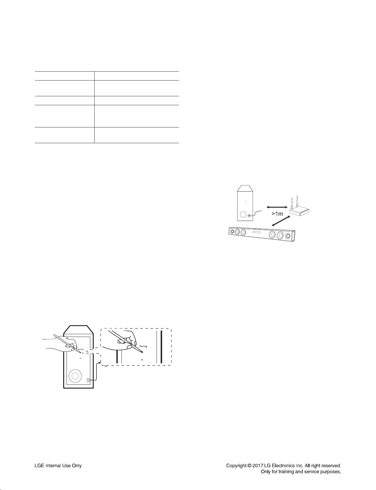
WIRELESS SUBWOOFER CONNECTION
LED indicator of wireless subwoofer
LED Color Status
Green
(Blink)
Attempting to make connection.
Green The connection is completed.
Red
The wireless subwoofer
is in standby mode
or the connection is failed.
Off
(No display)
The power cord of wireless
subwoofer is disconnected.
Setting up the wireless subwoofer
for the first time
1. Connect the power cord to the subwoofer and plug
the power cord into a power outlet.
2. Turn on the main unit : The sound bar and wireless
subwoofer will be automatically connected.
- Green LED on the rear of wireless subwoofer
turns on.
Manually pairing wireless subwoofer
When your connection is not completed, you can
check red LED on the wireless subwoofer and the
wireless subwoofer does not make sound. To solve
the problem, follow the steps below.
1. Press Pairing button on the rear of the wireless
subwoofer.
- The green LED on the rear of the wireless
subwoofer blinks quickly.
2. Turn on the main unit.
3. Pairing is completed.
- The green LED on the rear of the wireless
subwoofer turns on.
Note
:
•It takes a few seconds (and may take longer) for the
main unit and the subwoofer to communicate with
each other and make sounds.
•The closer the main unit and the subwoofer, the
better sound quality. It is recommended to install the
main unit and the subwoofer as close as possible
and avoid the cases below.
- There is a obstacle between the main unit and the
subwoofer.
- There is a device using same frequency with this
wireless connection such as a medical equipment,
a microwave or a wireless LAN device.
- Keep the sound bar and the subwoofer away from
the device (ex. wireless router, microwave oven,
etc.) over 1m to prevent wireless interference.

1-5
HIDDEN KEY MODE
HIDDEN MODE KEYS
Option EDIT Main unit 'VOL-' + Remote Control 'NIGHT ON'
Initialize Main unit 'VOL-' + Remote Control 'ASC'
Version Check Main unit 'VOL-' + Remote Control 'Play'
Clip Off
Main unit 'VOL-' + Remote Control 'Function'Clip On
Clip On Gain Monitoring
Wireless RF Change
Enter : Main unit 'VOL-' + Remote Control 'B.Skip'
Setting : B.Skip/F.Skip
Exit : Play/Pause"
BYPASS Sound Effect Main unit 'VOL-' + Remote Control 'AUTO POWER OFF'
APD Time Display Main unit 'VOL-' + Remote Control 'WOOFER LEVEL -'
APD On/Off Main unit 'VOL-' + Remote Control 'F.Skip'
Up Play/Pause
Down B.Skip
Right F.Skip
Left WOOFER LEVEL+
Enter AUTO POWER ON
Demo Mode (Play) Main unit 'Volume minimum state' + Remote Control 'function'
For 7seconds
Wireless Demo Mode Main unit 'VOL-' + Remote Control 'B.Skip'
TV Remocon On/Off Remote Control 'NIGHT OFF' + Remote Control '+' For 3seconds
BT Name Display Remote Control 'B.Skip' + Remote Control '+' For 2seconds
BT Lock Remote Control 'AUTO POWER OFF' + Remote Control '+'
For 2seconds
Wireless Factory Main unit 'Volume minimum state' + Remote Control 'MUTE'
For 3seconds
BT SIG Critification Main unit 'VOL-' + Remote Control 'NIGHT OFF' For 3seconds
1-6
1. Preparation
- Remote control.
- Do format USB Memory to FAT32 File system.
- USB : Update file exist only in the USB Memory stick.
Ex ) SJ3 :
ESS E:\DSP_SJ3_*.rom (if USB driver is E:\)
EQ E:\EQ_PRG.BIN (if USB driver is E:\)
Wireless Tx E:\WIRELESS_TX.bin (if USB driver is E:\)
Wireless Rx E:\WIRELESS_RX.bin (if USB driver is E:\)
2. Update
1) Power on.
2) Select the USB function.
3) Insert USB.
4) Never remove USB or AC cord while updating.
5) After update finish, power will be off automatically.
6) Power cord un-plug.
ESS / EQ PROGRAM UPDATE GUIDE

1-7
SPECIFICATIONS
• GENERAL
Power requirements Refer to main label.
Power consumption Refer to main label.
Networked standby : 0.5 W
(If all network ports are activated.)
Dimensions (W x H x D) Approx. 950 mm x 71 mm x 47 mm
Operating temperature 5 °C to 35 °C
Operating humidity 5 % to 90 %
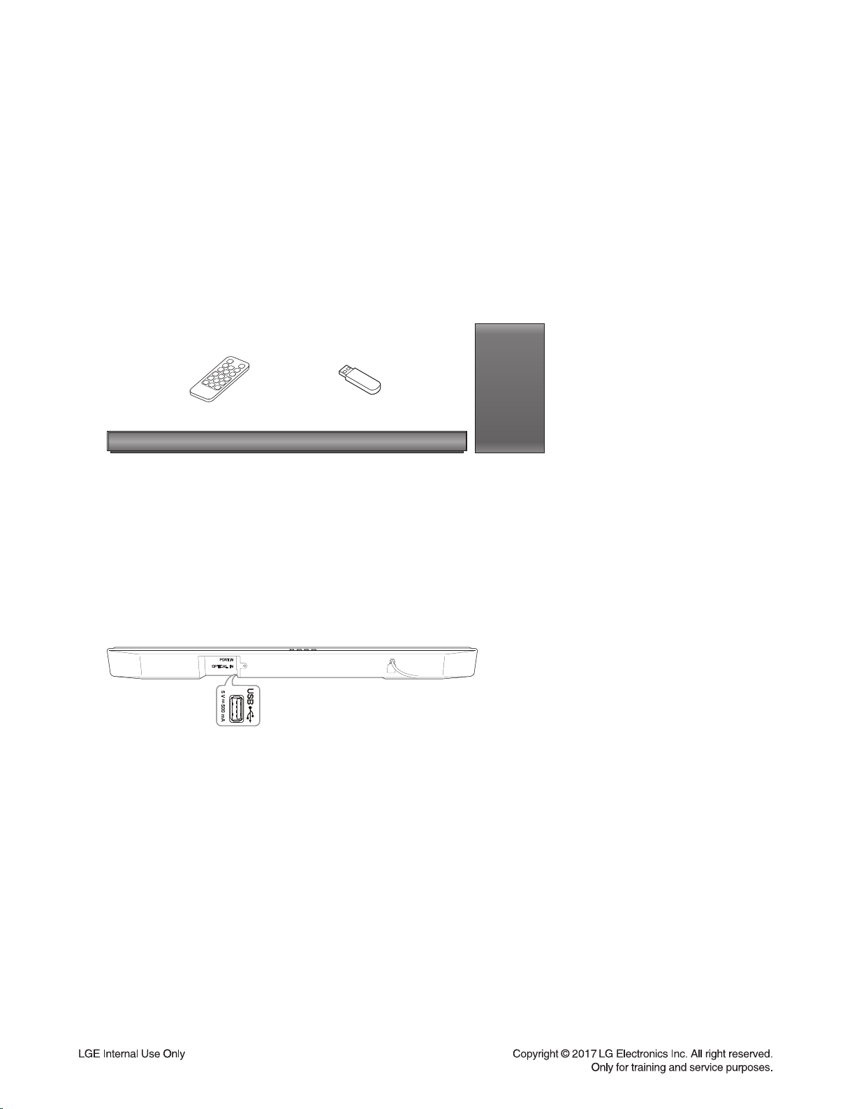
Bus Power Supply 5 V 500 mA
Available Digital Input Audio Sampling Frequency 32 kHz, 44.1 kHz, 48 kHz, 88.2 kHz, 96 kHz
Available Digital Input Audio format Dolby Digital, DTS Digital Surround, PCM
• INPUTS
OPTICAL IN (Digital audio in) 3 V (p-p), Optical jack x 1
PORT. IN (Portable in) 0.5 Vrms (3.5 mm stereo jack) x 1
• AMPLIFIER (RMS Output power)
Total 300 W RMS
Front 50 W RMS x 2 (4 Ωat 1 kHz, 10 % THD)
Subwoofer 200 W RMS (3 Ωat 80 Hz, 10 % THD)
• WIRELESS SUBWOOFER
Power requirements Refer to main label on the subwoofer.
Power consumption Refer to main label on the subwoofer.
Type 1 Way 1 Speaker
Impedance 3 Ω
Rated Input Power 200 W RMS
Max. Input Power 400 W RMS
Dimensions (W x H x D) Approx. 171 mm x 320 mm x 252 mm
•Designs and specifications are subject to change without prior notice.

1-8

2-1
SECTION 2
CABINET & MAIN CHASSIS
CONTENTS
EXPLODED VIEWS ........................................................................................................................................... 2-3
1. MAIN SET SECTION ................................................................................................................................ 2-3
2. WIRELESS SUBWOOFER SECTION...................................................................................................... 2-5
3. PACKING ACCESSORY SECTION ......................................................................................................... 2-7
Other manuals for SJ3
6
This manual suits for next models
1
Table of contents
Other LG Speakers System manuals


