LG LFC20740 Series User manual
CAUTION
BEFORE SERVICING THE UNIT,
READ THE SAFETY PRECAUTIONS IN THIS MANUAL.
REFRIGERATOR
SERVICE MANUAL
MODELS:
LFC20740**

CONTENTS
-2-
Please read the following instructions before servicing your
refrigerator.
1.Check the refrigerator for current leakage.
2.To prevent electric shock,unplug before servicing.
3.Always check line voltage and amperage.
4.Use standard electrical components.
5.Don't touch metal products in the freezer with wet
Hands.This may cause frost bite.
6.Prevent water from spiling on to electric elements or the
Machine parts.
7.Before tilting the refrigerator,remove all materials from
On or in the refrigerator.
8.When servicing the evaporator,wear gloves to prevent
Injuries from the sharp evaporator fins.
9.Service on the refrigerator should be performed by a
Qualified technician.Sealed system repair must be
Performed by a CFC certified technician.
SAFETYPRECAUTIONS
SAFETY PRECAUTIONS
1. SPECIFICATIONS
2. PARTS IDENTIFICATION
3. DISASSEMBLY
3.1 DOOR
3.2 DOOR ALIGNMENT
3.3 FAN AND FAN MOTOR
3.4 DEFROST CONTROL ASSEMBLY
3.5 LAMP
3.6 REFRIGERATOR CONTROL BOX
3.7 MULTI DUCT
4. ADJUSTMENT
4.1 COMPRESSOR
4.2 PTC-STARTER
4.3 OLP (OVERLOAD PROTECTOR)
4.4 TO REMOVE THE COVER PTC
5. CIRCUIT DIAGRAM
6. TROUBLESHOOTING
6.1COMPRESSOR AND ELECTRICAL COMPONENTS
6.2 PTC AND OLP
6.3 OTHER ELECTRICAL COMPONENTS
6.4 SERVICE DIAGNOSIS CHART
6.5 REFRIGERATION CYCLE
7. OPERATION PRINCIPLE AND REPAIR METHOD OF ICEMAKER
8. DESCRIPTION OF FUNCTION & CIRCUIT OF MICOM
9. EXPLODED VIEW & REPLACEMENT PARTS LIST
………………………………………………………………. 5
………………………………………………………………. 5
………………………………………………………………. 6
………………………………………………………………. 7
………………………………………………………………. 2
………………………………………………………………. 3
………………………………………………………………. 4
………………………………………………………………. 8
………………………………………………………………. 8
………………………………………………………………. 7
………………………………………………………………. 7
………………………………………………………………. 7
………………………………………………………………. 7
………………………………………………………………. 8
………………………………………………………………. 9
……………………………………………………………….10
……………………………………………………………….11
………………………………………………………………. 9
……………………………………………………………….13
……………………………………………………………….17
……………………………………………………………….20
……………………………………………………………….40
……………………………………………………………….11
……………………………………………………………….12
……………………………………………………………….14
……………………………………………………………….15

1. SPECIFICATIONS
- 3-
HANDLE TYPE CURVED
REVERSIBLE DOOR NO
DOOR FINISH STAINLESS
STEEL/PCM/VCM
BASKET DOOR NO
LAMP YES(1)
YES(1)
TRAY MEAT(SNACK PAN) YES(1)
SHELF 4fIX
MAGIC CRISPER NO
LAMP YES(2)
TRAY EGG
GUIDE BOTTLE YES(2)
TRAY VEGETABLE NORMAL
NO
REFRIGERATOR
BASKET DOOR 3 LEFT+3RIGHT
REFRIGERANT/gr
MODELS
SPECIFICATIONS
LFC20740**
180.97/374.23/555.20
29 7/8*68 3/7*34 5/9
111
R134a 120±3gr
NO
FREEZER
ICE TRAY
GENERAL FEATURES
SHELF
CAPACITY litros(F/R/T)
DIMENSIONS in(W*H*D)
WEIGHT kg

- 4 -
2. PARTS IDENTIFICATION
Use this section to become more familiar with the parts and features.
NOTE:This guide covers several different models.The refrigerator you have purchased may have some
or all of the items listed below.The locations of the features shown below may not match your model.
*on some models
A
B
C
G
H
I
J
E
F
K
D
L
M
N
O
P
AL
Digital Sensor Control
Durabase
Divider
Egg Box
Refrigerator Door Rack
Freezer Light
Pull out Drawer
B
C
D
F
E
G
H
I
J
K
M
N
O
P
Ice Tray *
Optibin Crisper
Keeps fruits and vegetable fresh and crisper
Snack Pan
Can Dispenser*
Temperature Control*
Shelves
Refrigerator Light
Customcube Icemaker*
Dairy Bin
*

3-1 DOOR 2. Remove gasket bracket clips
There are two clips on each door. Start bracket removal
near one of the middle clips.
1) Pull gasket back to expose gasket bracket clip and
door frame.
2) Insert a flat tip screwdriver into seam between gasket
bracket and door frame and pry back until clips snaps
out.
3) Continue prying back along seam until all clips snap
out.
3. Remove gasket
Pull gasket free from gasket channel on the three
remaining sides of door.
Door Gasket Replacement
1. Insert gasket bracket clips
1) Insert gasket bracket edge beneath door frame edge.
2) Turn upper gasket bracket spring so that both spring
ends are in the door channel.
3) Push in clip until you hear it snap securely into place.
4) Push in remaining two clips until you hear each snap
securely into place.
Note: Make sure that no part of gasket bracket edge
protrudes from beneath door frame edge.
3. DISASSEMBLY
- 5-
Frame Cover
Handle
Gasket
Door Bracket Clip
Frame
Flat Tip
Screwdriver
Gasket
Bracket
Figure 3
Figure 1
Figure 2
Figure 4
Gasket
Bracket Clip
Spring
Door
Frame Correct Incorrect
Figure 5
Left Door
Loosen the cover screw (1).
Disconnect door switch wire (2).
Loosen hinge bolts (3).
Lift off the top hinge (4).
Place the door on a non-scratching surface with
the inside up.
the inside up.
Door Gasket Removal
1. Remove door frame cover
Starting at top of cover and working down, snap cover
out and away from door.
Right Door
Loosen the cover screw (1).
Disconnect door switch wire (2).
Loosen hinge bolts (3).
Lift off the top hinge (4).
Place the door on a non-scratching surface with
Loosen ground screw (6).
Disconnect wire harness (5).
Left Right

2. Insert gasket into channel
1) Snap gasket assembly into the door bracket.
<Inserting the Gasket Assembly into the Bracket Door>
2) Press gasket into channels on the three remaining
sides of door.
3. Replace door frame cover
Starting at top of cover and working down, snap cover
back into door.
3-2 DOOR ALIGNMENT
If the space between your doors is uneven, follow the
instructions below to align the doors:
1. With one hand, lift up the door you want to raise at
middle hinge.
2. With other hand, use pliers to insert snap ring as shown.
3. Insert additional snap rings until the doors are aligned.
(Three snap rings are provided with unit.)
- 6 -
Figure 6
Correct
Incorrect
Figure 7
Figure 8
Figure 9

3-3 FAN AND FAN MOTOR
1. Remove the freezer shelf. (If your refrigerator has an
icemaker, remove the icemaker first)
2. Remove the plastic guide for slides on left side by
unscrewing phillips head screws.
3. Remove the grille by removing one screw and pulling the
grille forward.
4. Remove the Fan Motor assembly by loosening 2 screws
and disassembling the shroud.
5. Pull out the fan and separate the Fan Motor and Bracket.
3-4 DEFROST CONTROL ASSEMBLY
Defrost Control assembly consists of Defrost Sensor and
FUSE–M.
The Defrost Sensor works to defrost automatically. It is
attached to the metal side of the Evaporator and senses its
temperature. At 72°C, it turns the Defrost Heater off.
Fuse-M is a safety device for preventing over-heating of
the Heater when defrosting.
1. Pull out the grille assembly. (Figure 12)
2. Separate the connector with the Defrost Control
assembly and replace the Defrost Control assembly
after cutting the Tie Wrap. (Figure 13)
3-5 LAMP
3-5-1 To change the refrigerator light (figure 14)
(Max. 60 W2EA).
3-5-2 Freezer Compartment Lamp (figure 15)
1. Unplug refrigerator or disconnect power.
2. Reach behind light shield to remove bulb.
3. Replace bulb with a 60-watt appliance bulb.
4. Plug in refrigerator or reconnect power.
3-6 CONTROL BOX-REFRIGERATOR
1. First, remove all shelves in the refrigerator, than remove
the Refrigerator control Box by loosening 2 screws.
2. Remove the Refrigerator Control Box by pulling it
downward.
3. Disconnect the lead wire on the right position and
separate the lamp sockets.
3-7 MULTI DUCT
1. Remove the upper and
lower Caps by using a flat
screwdriver, and remove 2
screws. (Figure 17)
2. Disconnect the lead wire
on the bottom position.
-7- -
GRILLE ASSEMBLY
Figure 12
DEFROST-CONTROL
ASSEMBLY
Figure 13
Figure 14
Figure 15
CONTROL BOX
COVER LAMP
Figure 16
Figure 17
GRILLE
FAN MOTOR
FAN
BRACKET
MOTOR
Figure 11
1. Unplug the power cord from the outlet.
2. Remove refrigerator shelves.
3.
4.Turn the bulb counterclockwise.
5. To assemble, first insert the hooks at the back and
Release the hooks on the front of the light shield
with the help of a flat screwdriver and pull the
shield down to remove it.
then push up the light shield upwards.
4-1 COMPRESSOR
4-1-1 Role
The compressor intakes low temperature and low pressure
gas from the evaporator of the refrigerator and compresses
this gas to high-temperature and high-pressure gas. It then
delivers the gas to the condenser.
4-1-2 Composition
The compressor includes overload protection. The PTC
starter and OLP (overload protector) are attached to the
outside of the compressor. Since the compressor is
manufactured to tolerances of 1 micron and is hermetically
sealed in a dust and moisture-free environment, use
extreme caution when repairing it.
4-1-3 Note for Usage
(1) Be careful not to allow over-voltage and over-current.
(2) If compressor is dropped or handled carelessly, poor
operation and noise may result.
(3) Use proper electric components appropriate to the
Particular Compressor in your product.
(4) Keep Compressor dry.
If the Compressor gets wet (in the rain or a damp
environment) and rust forms in the pin of the Hermetic
Terminal, poor operation and contact may result.
(5) When replacing the Compressor, be careful that dust,
humidity, and soldering flux don’t contaminate the inside
of the compressor. Contamination in the cylinder may
cause noise, improper operation or even cause it to
lock up.
4-2 PTC-STARTER
4-2-1 Composition of PTC-Starter
(1) PTC (Positive Temperature Coefficient) is a no-contact
semiconductor starting device which uses ceramic
material consisting of BaTiO3.
(2) The higher the temperature is, the higher the resistance
value. These features are used as a starting device for
the Motor.
4-2-2 Role of PTC-Starter
(1) The PTC is attached to the Sealed Compressor and is
used for starting the Motor.
(2) The compressor is a single-phase induction motor.
Durign the starting operation, the PTC allows current
flow to both the start winding and main winding.
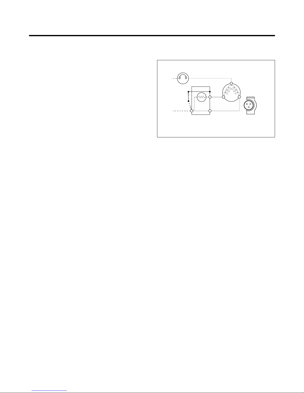
4-2-3 PTC-Applied Circuit Diagram
•Starting Method for the Motor
4-2-4 Motor Restarting and PTC Cooling
(1) It requires approximately 5 minutes for the pressure to
equalize before the compressor can restart.
(2) The PTC device generates heat during operation.
Therefore, it must be allowed to cool before the
compressor can restart.
4-2-5 Relation of PTC-Starter and OLP
(1) If the compressor attempts to restart before the PTC
device is cooled, the PTC device will allow current to
flow only to the main winding.
(2) The OLP will open because of the over current
condition. This same process will continue (3 to 5
times) when the compressor attempts to restart until
the PTC device has cooled. The correct OLP must be
properly attached to prevent damage to the
compressor.
Parts may appear physically identical but could have
different electrical ratings. Replace parts by part
number and model number. Using an incorrect part
could result in damage to the product, fire, injury, or
possibly death.
4-2-6 Note for Using the PTC-Starter
(1) Be careful not to allow over-voltage and over-current.
(2) Do not drop or handle carelessly.
(3) Keep away from any liquid.
If liquid such as oil or water enters the PTC,
PTC materials may fail due to breakdown of their
insulating capabilities.
(4) If the exterior of the PTC is damaged, the resistance
value may be altered. This can cause damage to the
compressor and result in a no-start or hard-to-start
condition.
(5) Always use the PTC designed for the compressor and
make sure it is properly attached to the compressor.
Parts may appear physically identical but could have
different electrical ratings. Replace parts by part
number and model number. Using an incorrect part
could result in damage to the product, fire, injury, or
possibly death.
4. ADJUSTMENT
-8--
PTC STARTER SEALED
TERMINAL
COMPRESSOR
MOTOR
C
M
SM
36
5
2
S
PTC
N
L1
OVERLOAD PROTECTOR
Resistance Starter Capacitor Running
Figure 17
4-3 OLP (OVERLOAD PROTECTOR)
4-3-1 Definition of OLP
(1) OLP (OVERLOAD PROTECTOR) is attached to the
Compressor and protects the Motor by opening the
circuit to the Motor if the temperature rises and
activating the bimetal spring in the OLP.
(2) When high current flows to the Compressor motor, the
Bimetal works by heating the heater inside the OLP,
and the OLP protects the Motor by cutting off the
current flowing to the Compressor Motor.
4-3-2 Role of the OLP
(1) The OLP is attached to the Sealed Compressor used
for the Refrigerator. It prevents the Motor Coil from
being started in the Compressor.
(2) For normal operation of the OLP, do not turn the Adjust
Screw of the OLP in any way.
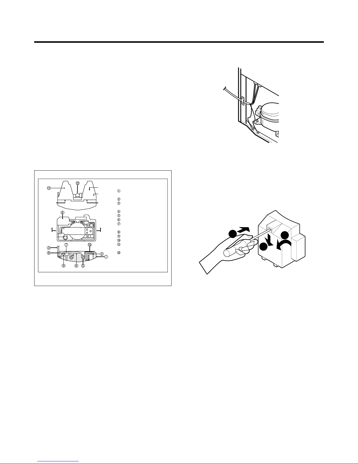
4-4 TO REMOVE THE COVER PTC
1) Remove the Cover Back M/C.
(2) Disconnect two housing upper side of comp connected
in.
(3) Loosen two screws on comp base.
(4) Use a L-shaped flap tool to pry off the cover.
(5) Assembly in reverse order of disassembly.
- 9 -
Part
Customer part
number
Lot code/
date code
330 FBYY -S1 BOX98
12345678
Physical
termination
part number
Electrical
characteristics
part number
No. Name
Base, phenolic
(UL 94 V-0 rated)
Movable arm support, plated steel
Stationary contact support,
plated steel
Heater support, plated steel
Heater, resistance alloy
Disc, thermostatic alloy
Movable arm, spring temper
copper alloy
Contact, movable, silver on copper
Contact, stationary, silver on copper
Slug, plated steel
Cover, polyester
(UL 94 V-0 rated)
Pin connector, plated copper alloy
(To engage 2.33/2.66 mm dia. pin)
(OVERLOAD PROTECTOR cross section)
Figure 18
2
3
1

5. CIRCUIT DIAGRAM
- 10 -
Other manuals for LFC20740 Series
2
Table of contents
Other LG Refrigerator manuals


LG
LG LSXC22396 Series User manual

LG
LG GBB72NSVCN1 User manual

LG
LG Fridge freezer User manual

LG
LG LRMXC2206 Series User manual

LG
LG LM78SXT User manual

LG
LG LLMXS3006S.ASTCNA0 User manual

LG
LG GR-B362CLC User manual

LG
LG GR-L196TLQA.CPLQGSF User manual

LG
LG GHB-247DVE User manual

LG
LG GR-M787DID User manual