LG 42PT85-ZB User manual
PLASMA TV
SERVICE MANUAL
CAUTION
BEFORE SERVICING THE CHASSIS,
READ THE SAFETY PRECAUTIONS IN THIS MANUAL.
CHASSIS : PD74A
MODEL : 42PT85 42PT85-ZB
website:htt ://biz.LGservice.com
Internal Use Only

- 2 - LGE Internal Use OnlyCopyright©2007 LG Electronics. Inc. All right reserved.
Only or training and service purposes
CONTENTS
SAFETY PRECAUTIONS ....................................................................................3
SPECIFICATIONS ................................................................................................4
ADJUSTMENT INSTRUCTIONS .........................................................................6
TROUBLE SHOOTING GUIDE..........................................................................13
BLOCK DIAGRAM.............................................................................................26
EXPLODED VIEW..............................................................................................2
EXPLODED VIEW PARTS LIST ........................................................................29
REPLACEMENT PARTS LIST...........................................................................30
SCHEMATIC DIAGRAM.........................................................................................
PRINTED CIRCUIT DIAGRAM ..............................................................................

- 3 - LGE Internal Use OnlyCopyright©2007 LG Electronics. Inc. All right reserved.
Only or training and service purposes
SAFETY PRECAUTIONS
Many electrical and mechanical parts in this chassis have special sa ety-related characteristics. These parts are identi ied by in the
Schematic Diagram and Replacement Parts List.
It is essential that these special sa ety parts should be replaced with the same components as recommended in this manual to prevent
X-RADIATION, Shock, Fire, or other Hazards.
Do not modi y the original design without permission o manu acturer.
General Guidance
An isolation Transformer should always be used during the
servicing o a receiver whose chassis is not isolated rom the AC
power line. Use a trans ormer o adequate power rating as this
protects the technician rom accidents resulting in personal injury
rom electrical shocks.
It will also protect the receiver and it's components rom being
damaged by accidental shorts o the circuitry that may be
inadvertently introduced during the service operation.
I any use (or Fusible Resistor) in this monitor is blown, replace it
with the speci ied.
When replacing a high wattage resistor (Oxide Metal Film Resistor,
over 1W), keep the resistor 10mm away rom PCB.
Keep wires away rom high voltage or high temperature parts.
Due to high vacuum and large sur ace area o picture tube,
extreme care should be used in handling the Picture Tube.
Do not li t the Picture tube by it's Neck.
Leakage Current Cold Check(Antenna Cold Check)
With the instrument AC plug removed rom AC source, connect an
electrical jumper across the two AC plug prongs. Place the AC
switch in the on position, connect one lead o ohm-meter to the AC
plug prongs tied together and touch other ohm-meter lead in turn to
each exposed metallic parts such as antenna terminals, phone
jacks, etc.
I the exposed metallic part has a return path to the chassis, the
measured resistance should be between 1MΩ and 5.2MΩ.
When the exposed metal has no return path to the chassis the
reading must be in inite.
An other abnormality exists that must be corrected be ore the
receiver is returned to the customer.
Leakage Current Hot Check (See below Figure)
Plug the AC cord directly into the AC outlet.
Do not use a line Isolation Transformer during this check.
Connect 1.5K/10watt resistor in parallel with a 0.15uF capacitor
between a known good earth ground (Water Pipe, Conduit, etc.)
and the exposed metallic parts.
Measure the AC voltage across the resistor using AC voltmeter
with 1000 ohms/volt or more sensitivity.
Reverse plug the AC cord into the AC outlet and repeat AC voltage
measurements or each exposed metallic part. Any voltage
measured must not exceed 0.75 volt RMS which is corresponds to
0.5mA.
In case any measurement is out o the limits speci ied, there is
possibility o shock hazard and the set must be checked and
repaired be ore it is returned to the customer.
Leakage Current Hot Check circuit
1.5 Kohm/10W
To Instrument's
exposed
METALLIC PARTS
Good Earth Ground
such as WATER PIPE,
CONDUIT etc.
AC Volt-meter
IMPORTANT SAFETY NOTICE
0.15uF

- 4 - LGE Internal Use OnlyCopyright©2007 LG Electronics. Inc. All right reserved.
Only or training and service purposes
SPECIFICATIONS
NOTE : Speci ications and others are subject to change without notice or improvement
.
VApplication Range
This spec is applied to the 42” PLASMA TV used PP7BA Chassis.
V Specification
Each part is tested as below without special appointment.
1) Temperature : 25±5°C (77±9°F), CST : 40±5
2) Relative Humidity: 65±10%
3) Power Voltage: Standard Input voltage (100-240V~, 50/60Hz)
* Standard Voltage o each product is marked by models.
4) Speci ication and per ormance o each parts are ollowed each drawing and speci ication by part number in accordance with SBOM.
5) The receiver must be operated or about 20 minutes prior to the adjustment.
VTest Method
1) Per ormance : LGE TV test method ollowed.
2) Demanded other speci ication
Sa ety : CE, IEC speci ication
EMC : CE, IEC
VGeneral Specification ( 42” XGA Module)
Display Screen Device
Aspect Ratio
PDP Module
Operating Environment
Storage Environment
Input Voltage
1
2
3
4
5
6
No Item Speci ication Remark
42” Wide Color Display Module
16:9
PDP42X4A,
RGB Closed Type
1)Temp. : 0~40deg
2)Humidity : 20~80%
3)Temp. : -20~60deg
4)Humidity : 10~90%
100-240V~, 50/60Hz
Plasma Display Panel
Film Filter
LGE SPEC.
Maker : LG
Chassis
PD74A 42PT85 UK,France, Germany, Spain,
Sweden, Finland, Italy
LG
Model Name Market Brand Remark
42PT85 Sa ety : IEC/EN60065
EMI : EN55013, EMS : EN55020
UK,France, Germany, Spain,
Sweden, Finland, Italy
Model ApplianceMarket
Not yet TEST
Remark

- 5 - LGE Internal Use OnlyCopyright©2007 LG Electronics. Inc. All right reserved.
Only or training and service purposes
VModule Specification
Market
Broadcasting system
Receiving system
SCART Jack(2EA)
Video Input (2EA)
S-Video Input (1EA)
Component Input (1EA)
RGB Input
HDMI Input(2EA)
Audio Input(4EA)
1
2
3
4
5
6
7
8
9
10
No Item Speci ication Remark
UK,France, Germany, Spain,
Sweden, Finland, Italy
1) PAL-BG
2) PAL - DK
3) PAL - I, I’
4) DVB - T(ID TV)
Analog : Upper Heterodyne
Digital : COFDM
PAL, SECAM
PAL, SECAM, NTSC
PAL, SECAM, NTSC
Y/Cb/Cr, Y/Pb/Pr
RGB-PC
RGB-DTV
HDMI-PC
HDMI-DTV & SOUND
PC Audio, Component, AV(2EA)
UK,France, Germany, Spain,
Sweden, Finland, Italy
Scart 1 Jack is Full scart and support RF-OUT
(analog)
Scart 2 Jack is Hal scart and support MNT-OUT
4 System : PAL, SECAM, NTSC, PAL60
4 System : PAL, SECAM, NTSC, PAL60
L/R Input

- 6 - LGE Internal Use OnlyCopyright©2007 LG Electronics. Inc. All right reserved.
Only or training and service purposes
ADJUSTMENT INSTRUCTIONS
1. Application Object
These instructions are applied to all o the 42” PLASMA TV,
PD74A Chassis.
2. Note
(1) Because this is not a hot chassis, it is not necessary to use
an isolation trans ormer. However, the use o isolation
trans ormer will help protect test instrument.
(2) Adjustment must be done in the correct order.
(3) The adjustment must be per ormed in the circumstance o
25±5°C o temperature and 65±10% o relative humidity i
there is no speci ic designation.
(4) The input voltage o the receiver must keep 100-240V~,
50/60Hz.
(5) Be ore adjustment, execute Heat-Run or 30 minutes at RF
no signal.
3. Channel memory Setting Method
: You can set channel memory by R/C or adjustment.
1)
Press ADJ key o Adjust Remote Controller.(P/N:105-210M)
2) Select ‘Channel Recover’ by using D/E(CH +/-) key, and
press ‘VOL +’.
3) The set is turned o automatically.
4) Press ‘power’ key o Adjust Remote Controller.
4. PCMCIA CARD Checking Method
: You must adjust DTV ##(Scrambled) Channel and insert
PCMCIA CARD to socket.
1) I PCMCIA CARD works normally, normal signals display
on screen.
But it works abnormally, “No CA module” words display on
screen.
5. POWER PCB Assy Voltage
Adjustments (Va, Vs Voltage adjustments)
5-1. Test Equipment : D.M.M. 1EA
5-2.Connection Diagram for Measuring
: re er to Fig.1
5-3. Adjustment Method
(1) Va Adjustment
1) A ter receiving 100% Full White Pattern, HEAT RUN.
2) Connect + terminal o D.M.M to Va pin o P12(P812),
connect - terminal to GND pin o P12(P812).
3) A ter turning VR901, voltage o D.M.M adjustment as
same as Va voltage which on label o panel right/top.
(Deviation; ±0.5V)
(2) Vs Adjustment
1) Connect + terminal o D.M.M to Vs pin o P812, connect
– terminal to GND pin o P812.
2) A ter turning VR951, voltage o D.M.M adjustment as
same as Va voltage which on label o panel right/top.
(Deviation; ±0.5V)
Each PCB assembly must be checked by check JIG set.
(Because power PCB Assembly damages to PDP Module,
especially be care ul)
(Fig.1) Connection diagram o power adjustment or measuring
<42” EAY3292701>

- 7 - LGE Internal Use OnlyCopyright©2007 LG Electronics. Inc. All right reserved.
Only or training and service purposes
6. EDID (The Extended Display
Identification Data)/ DDC (Display
Data Channel) download
* Caution
(1) Use the proper signal cable or EDID Download.
- Analog EDID : Pin3 exists.
- Digital EDID : Pin3 exists.
(2) Never connect HDMI & DVI-D & DVI-A Cable at the same
time.
(3) Use the proper cables below or EDID Writing.
6-1. EDID Date
6-2. Setting of device
6-3. Preparation for Adjustment
1) As above Fig. 2, Connect the Set, EDID Download Jig, PC
& Cable.
2) Turn on the PC & EDID Download Jig. And Execute the
S/W : EDID TESTER Ver,2.5.
3) Set up S/W option.
Repeat Number : 5
Device Address : A0
PageByte :
4) Power on the Set.
6-4. Sequence of Adjustment
- EDID Download
1) Init the data.
2) Load the EDID data.(Open File).
[Analog ile] ( or RGB)
[Digital ile] ( or HDMI)
3) Set the S/W as below.
4) Push the “Write Data & Veri y”button. And con irm “Yes”.
5) I the writing is inished, you will see the “OK” message.
6) I TV has two HDMI, you must download two times or
each HDMI.
(Fig. 2) Connection Diagram o DDC download
Open FileOpen File
Item
Manu acturer ID
Version
Revision
Condition
GSM
Digital : 1
Digital : 3
Hex Data
1E6D
01
03
For RGB EDID
D-sub to D-sub
For HDMI EDID
DVI-D to HDMI or HDMI to HDMI
- 8 - LGE Internal Use OnlyCopyright©2007 LG Electronics. Inc. All right reserved.
Only or training and service purposes
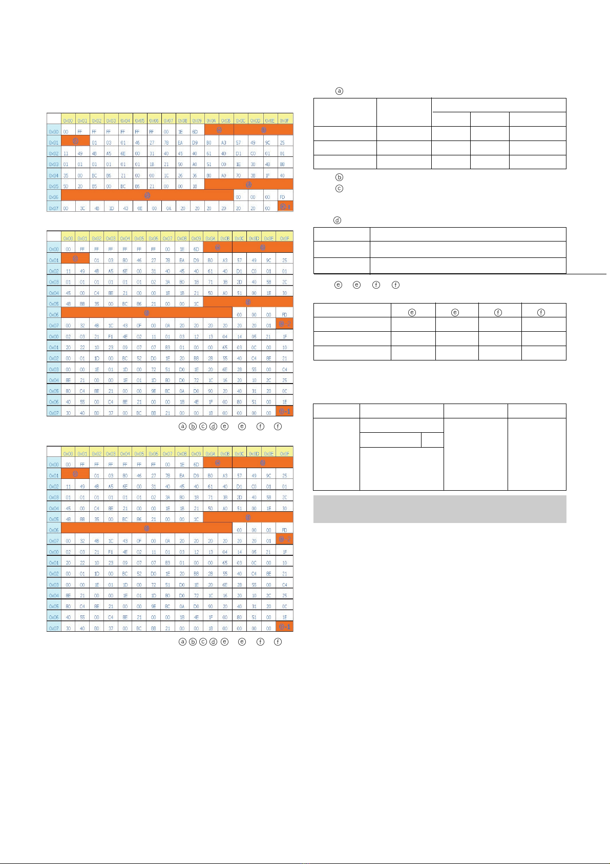
- EDID DATA
1) Analog RGB(128Byte).
2) HDMI1 RGB(256Byte).
=> Detail EDID Options are below( ,,,,-1, -2, -1, -2)
3) HDMI1 RGB(256Byte).
=> Detail EDID Options are below( ,,,,-1, -2, -1, -2)
1.
->
Product ID
2.
->
Serial No : Controlled on production line
3.
->
Month, Year : Controlled on production line
ex) Week : '03' => '03'
Year : '2006' => '10'
4.
->
Model Name(Hex):
5.
-1, -2, -1, -2 ->
Checksum : Changeable by total
EDID data
7. ADC Calibration
Model Name
42PT85-ZB
50PT85-ZB
-1
89
8A
-2
C2
C3
-1
CC
CC
-2
F2
BC
Model
Name
42PT85
50PT85
Product ID
Product ID EDID table
B69C
B69C
Dec Hex
9CB6
9CB6
Model Name
42PT85-ZB
50PT85-ZB
Hex Data
000000FC003432505438350A202020202020
000000FC003530505438350A202020202020
- System control RS-232 Host should be “PC“ or adjustment.
- Be ore AV ADC Calibration, execute the “Panel size selection“
ADC RF/AV/S-VIDEO Component RGB-PC
MSPG925FS PAL Model:215 (720P) Model: 60
INPUT SELECT AV3 Pattern:65 (1024*768 60Hz)
Model: 202 (PAL-BGDHI) 720P/50Hz Pattern: 65
Pattern: 65 7 Color Bar
PAL 7 Color Bar

- 9 - LGE Internal Use OnlyCopyright©2007 LG Electronics. Inc. All right reserved.
Only or training and service purposes
.
Auto RF/AV/S-VIDEO Color Balance
-1. Requirement
VThis AV color balance adjustment should be per ormed
be ore white Balance Adjustment.
-2. Required Equipment
1) Remote controller or adjustment.
2) MSPG-925FS Pattern Generator (Which has Video Signal:
7 Color Bar Pattern shown in Fig.3).
(1) Model: 202 / Pattern: 65 - Models use PAL-BGDHI.
(composite signal)
-3. Method of Auto RF/AV/S-VIDEO Color
Balance(PAL_BGDHI)
1) Input the PAL Video signal 7 color Bar (MSPG-925FS
Model : 202, pattern : 65) signal into AV3.
2) Set the PSM to Dynamic mode in the Picture menu.
3) Press INSTART key on R/C or adjustment.
4) Press the G(Vol. +) key operate to set, then it becomes
automatically.
5) Auto-RGB OK means completed adjustment.
9. Adjustment of Component
9-1. Requirement
VThis AV color balance adjustment should be per ormed
be ore white Balance Adjustment.
9-2. Required Equipment
1) Remote controller or adjustment.
2) MSPG-925FS Pattern Generator (Which has Video Signal:
7 Color Bar Pattern shown in Fig.5).
(1) Model: 215 / Pattern: 65 - Models use component.
9-3. Method of Auto Component Color Balance
1) Input the Component 720p/50Hz 7 Color Bar (MSPG-
925FS Model : 215, pattern : 65) signal into Component.
2) Set the PSM to Dynamic mode in the Picture menu.
3) Press IN-START key on R/C or adjustment.
4) Press the G(Vol. +) key to operate the set, then it becomes
automatically.
5) Auto-RGB OK means the adjustment is completed.
10. Adjustment of RGB
10-1. Requirement
VThis AV color balance adjustment should be per ormed
be ore white Balance Adjustment.
10-2. Required Equipment
1) Remote controller or adjustment.
2) MSPG-925FS Pattern Generator (Which has Video Signal:
7 Color Bar Pattern shown in Fig.7).
(1) Model: 3 / Pattern: 65 - Models use RGB
10-3. Method of Auto RGB Color Balance
1) Input the PC 1024x768 @ 60Hz 7 color bar (MSPG-925FS,
Model : 3, Pattern : 65) signal into RGB.(using D-sub to D-
sub cable)
2) Set the PSM to Dynamic mode in Picture menu.
3) Press the IN-START key on R/C or adjustment.
4) Press the G(Vol. +) key operate to set , then it becomes
automatically.
5) Auto-RGB OK means adjustment is completed.
(Fig.3) Color Bar signal
(Fig.4) Color Bar signal
(Fig.5) Color Bar signal
(Fig.6) Color Bar signal
(Fig.7) Color Bar signal
(Fig.8) Color Bar signal

11. Scart RGB(DVR) Adjustment Mode
11-1. Required Equipment
1) Remote controller or adjustment
2) MSPG-925FS Pattern Generator (Which has Video Signal:
7 Color Bar Pattern shown in Fig.9)
(1) Model: 232 / Pattern: 08
11-2. Method of Auto Scart RGB(DVB) Balance
1) Input the Video Signal : Color Bar signal into AV1(using Full
Scart Cable).
2) Set the PSM to Dynamic mode in Picture menu.
3) Press the IN-START key on R/C or adjustment.
4) Press the TURBO-PICTURE Key on R/C or adjustment.
5) Press the G(Vol. +) key operate To set , then it becomes
automatically.(Fig.7)
6) Scart RGB(DVR) OK means Scart RGB adjustment is
completed.
12. Adjustment of White Balance
12-1. Required Equipment
(1) Color Analyzer(CA-100+/CH.10)
1) Remote controller o adjustment -> Color Analyzer(CA-
100+ o same product) : CH 10
2) Auto W/B adjustment instrument.(only or Auto
Adjustment) -> AV Pattern Generator.
W Color temperature standards according to CSM and Module.
W
White balance adjustment coordinate and color temperature.
* PC( or communication through RS-232C)
-> UART Baud rate : 115200 bps
* Luminance Y AV : upper 150cd/m2 (Typ : 350cd/m2)
-> Applying to Cool, Medium, Warm mode.
12-2. Connection Picture of the Measuring
Instrument(On Automatic control)
(1) Inside PATTERN is used when W/B is controlled. Connect
to auto controller or push control R/C IN-START -> Enter
the mode o White-Balance, the pattern will come out.
power supply) and heat-run over 15 minutes.
- 10 - LGE Internal Use OnlyCopyright©2007 LG Electronics. Inc. All right reserved.
Only or training and service purposes
(Fig.10) Color bar Signal
(Fig.11) Auto AV(CVBS) Color Balance Test Pattern
Full White Pattern
RS-232C Communication
CA-210
Color
ANALYZER
TYPE : CA-210
(Fig.9) Color Bar signal
PLASMA Remark
11000K
9300K
6500K
Cool
Normal
Warm
CSM
Cool CS-100 CA-210(CH 10)
x 0.276 0.276±0.002
y 0.283 0.283±0.002
∆uv 0.000 0.000
Medium CS-100 CA-210(CH 10)
x 0.285 0.285±0.002
y 0.293 0.293±0.002
∆uv 0.000 0.000
Warm CS-100 CA-210(CH 10)
x 0.313 0.313±0.002
y 0.329 0.329±0.002
∆uv 0.004 0.004
This manual suits for next models
1
Table of contents
Other LG Plasma TV manuals


