LG M3204C User manual

www.lg.com
OWNER’S MANUAL
MONITOR SIGNAGE
MONITOR SIGNAGE MODELS
M3204C
Please read this manual carefully before operating
your set and retain it for future reference.
ENGLISH

2
Table of Contents
Accessories 3
Connecting the stand 4
Connecting the Speakers 5
To install Portrait 6
Using the Remote Control 7
Name and Function of the Parts 9
Connecting to External Devices 10
When Connecting to your PC............................................................................................ 10
When using the LAN........................................................................................................... 12
Daisy Chain Monitors ......................................................................................................... 13
VESA FDMI wall Mounting ................................................................................................. 14
Video Input ........................................................................................................................... 15
Component Input (480i/480p/576i/576p/720p/1080i) ...................................................... 16
HDMI Input (480p/576p/720p/1080i/1080p) ...................................................................... 17
User Menus 18
Screen Adjustment options............................................................................................... 18
OSD Menu ............................................................................................................................ 20
How to adjust the OSD (On Screen Display) screen ..................................................... 21
How to adjust the screen automatically .......................................................................... 21
Adjusting Screen Color...................................................................................................... 22
Adjusting the audio function............................................................................................. 28
Adjusting the timer function..............................................................................................29
Selecting the options .........................................................................................................30
Adjusts the tile options. .....................................................................................................32
Adjusts the USB options.................................................................................................... 34
Troubleshooting 48
Specifications 51
Controlling the Multiple Product A1

3
NC2000 kit
❖
Applicable only for models that support the NC2000.
Without prior notice, optional accessories are subject to change to improve the performance of the product, and
new accessories may be added.
❖
Optional accessories (purchased separately) may vary depending on the model.
❖
Note that optional accessories may look different from those shown here.
Thank you for your purchase. Please check the product as well as the accessories shown below
❖
Note that the accessories may look different from those shown here.
Speaker kit
❖
Applicable only for models that support the speakers.
Stand kit
❖
Applicable only for models that support the stand.
Remote Control
/ Batteries
CD-ROM / Cards
D-Sub Signal
Cable
Speaker(2)
NC2000 CD-ROM /
Cards
Screws (2)
Screws (4)
/ Cable (2)
Power Cable Audio Cable (PC)
Cable holder/Cable tie
They may not
be available
in some areas
or for some
models.
Accessories
Separate purchase
Accessories
Stand (2) Screws (4)

4
Connecting the stand
- Only on some models.
2.
3.
1. Take the parts for the stand out of the box and assemble them as shown in
the picture.
Place a soft cloth on the table and put the product with the screen facing
downward. Connect the stand as shown in the following picture.
Use the screws to secure the stand on the rear side of the product as
shown in the diagram.
First, check if the following parts are all present.
Stand (2)
Screws (4)
Parts

5
Connecting the Speakers
Mount the product onto the speaker by using a screw as shown in the following
connect the speaker cable.
When the speaker is installed.
*Connect the input terminal with a proper
color match.
Remove the paper.
Cable holder
After installing your speakers, use holders and cable ties to organize the speaker
cables.
* This feature is not available in all model.
Cable tie
* This feature is not available in all model.
- Only on some models.

6
To install Portrait
"When installing Portrait, rotate it clockwise based on its front."
- Only on some models.

7
P
A
G
E
INPUT
ENERGY
SAVING
MARK
ARC
ON
OFF
. , !
ABC
DEF
GHI
JKL
MNO
PQRS
TUV
1/a/A
- * #
WXYZ
CLEAR
OK
S.MENU
MONITOR
PSM
AUTO
MUTE
BRIGHT
NESS
MENU
ID
BACK TILE
ON OFF
EXIT
POWER
1
2
5
4
7
6
9
8
13
12
11
10
3
Using the Remote Control
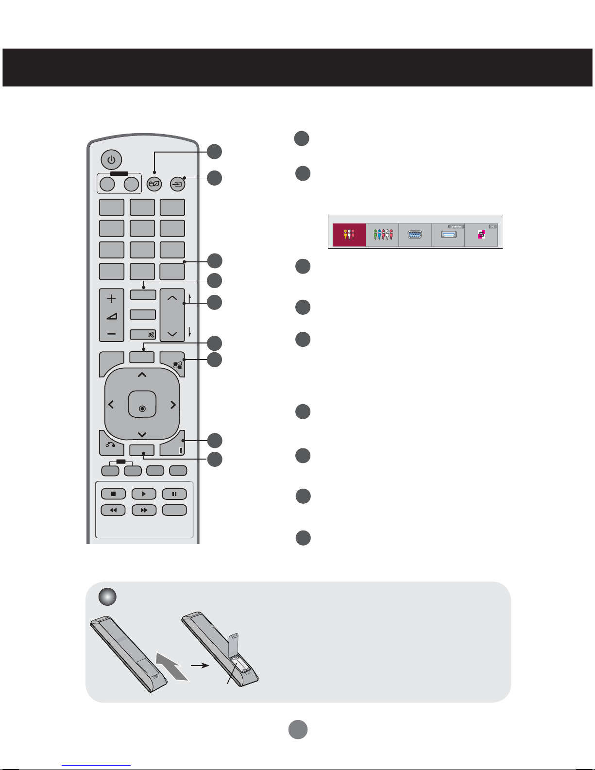
Name of the Remote Control Buttons
1
2
5
3
4
7
6
9
8
13
12
11
10
Power On / Off Button
- Switches the set on from standby or off to
standby.
Monitor On / Off Button
- Turn off the monitor and then turn it back on.
Number and Alphabet Buttons
- Type numbers and alphabets.
1/a/A Button
- Selects the number and alphabet.
(SuperSign input only)
Volume Up/Down Button
- Adjusts the volume.
PSM Button
- Selects the Picture Status Mode.
MUTE Button
- Switches the sound on or off.
MENU Button
- Selects a menu.
- Clears all on-screen displays and returns to
TV viewing from any menu.
Up/Down/Left/Right Buttons
- Allows you to navigate the on-screen menus
and adjust the system settings to your
preferenc.
OK Button
- Accepts your selection or displays the
current mode.
BACK button
- Allows the user to move
return one step in an interactive application.
ID ON/OFF Button
- When the number of input ID is equal to the
number of ID Mode, you can control the monitor
which you want in the multi display condition.
USB Menu control buttons
- Adjust the USB menu(Photo List, Music List
and Movie List ).

8
P
A
G
E
INPUT
ENERGY
SAVING
MARK
ARC
ON
OFF
. , !
ABC
DEF
GHI
JKL
MNO
PQRS
TUV
1/a/A
- * #
WXYZ
CLEAR
OK
S.MENU
MONITOR
PSM
AUTO
MUTE
BRIGHT
NESS
MENU
ID
BACK TILE
ON OFF
EXIT
POWER
14
15
18
16
19
17
20
21
22
Energy Saving Button
- Adjust the Energy Saving mode of the SET.
INPUT Select Button
If you press the button once, the following
Input Signal Window will appear. Select the
signal type you want using the ◄►button.
Clear button
- Delete the numbers and alphabets you
typed.(SuperSign input only)
ARC Button
- Selects the Aspect Ratio Mode
Brightness Key
- Adjust the resolution and brightness by
pressing the Up and Down buttons on the
remote control.
- In USB mode, the OSD menu has the Page
function to move to the next file list.
AUTO Button
- Automatically adjusts picture position and
minimizes image instability.(RGB input only)
S.MENU Button (SuperSign Menu Key)
- Selects the SuperSign OSD Menu.
(SuperSign input only)
EXIT Button
- Clears all on-screen displays and returns to monitor
viewing from any menu.
•
TILE button
- Selects the TILE Mode
Using the Remote Control
1. Slide off the battery cover.
2. Insert the batteries with correct polarity ( + / - ).
3. Close the battery cover.
4. To remove the batteries, perform the installation actions
in reverse.
• Dispose of used batteries in the recycle bin to prevent
environmental pollution.
Inserting batteries into remote control.
14
15
16
18
19
17
20
21
22
AAA Type
Input List
AV Component RGB HDMI/DVI SuperSign

9
Name and Function of the Parts
Rear View
* LINE OUT
A terminal used to connect to the speaker including a built-in amplifier (Amp). Make sure that
the connecting terminal of the PC sound card is checked before connecting. If the Audio Out of PC
sound card has only Speaker Out, reduce the PC volume. If the Audio Out of the PC sound card
supports both Speaker Out and Line Out, convert to Line Out using the card jumper of the program
(Refer to the Sound Card Manual).
* The product image in the user's guide could be different from the actual image.
Power Connector
Connect the power cord
RS-232C Serial Ports
RGB, HDMI/DVI Ports
HDMI Supports High Definition input and HDCP (High-bandwidth Digital
Content Protection). Some devices require HDCP in order to display HD
signals.
PC Sound Jack
Connect the audio cable to the *LINE OUT jack of the PC sound card.
Component, AV Ports
USB Port
LAN Port
Speaker Ports
1
2
4
3
6
5
8
7
1 2 43 65 87

10
First of all, see if the computer, product and the peripherals are turned off. Then, connect
the signal input cable.
When connecting with the D-Sub signal input cable.
When connecting with the HDMI-DVI signal input cable (not included).
* When HDMI PC is used, a compatiblity problem might occur.
MAC
Macintosh Adapter (not included)
Use the standard Macintosh adapter since an incompatible
adapter is available in the market. (Different signaling system)
Connecting to External Devices
Connect the power cord.
PC
PC/MAC
PC
PC
Connect the Audio cable.
(not included)
* User must use shielded signal interface cables (D-sub 15 pin cable, HDMI-DVI cable) with
ferrite cores to maintain standard compliance for the product.
When Connecting to your PC
1
2
3
B.
B.
A.
A.
Rear back of the set.
Other manuals for M3204C
1
This manual suits for next models
1
Table of contents
Other LG Monitor manuals