LG MB-4342W User manual

MICROW VE OVEN
SERVICE MANUAL
MODEL: MB-4342W
MH-6342W
CAUTION
BEFORE SERVICING THE UNIT, RE D THE
S FETY PREC UTIONS IN THIS M NU L.

This device is to be serviced only by properly qualified service personnel.
Consult the service manual for proper service procedures to assure continued safety operation and for precautions to be
taken to avoid possible exposure to excessive microwave energy.
PRECAUTIONS TO BE OBSERVED BEFORE AND
DURING SERVICING TO AVOID POSSIBLE
EXPOSURE TO EXCESSIVE MICROWAVE ENERGY
) Do not operate or allow the oven to be operated with the door open.
B) Make the following safety checks on all ovens to be serviced before activating the magnetron or other
microwave source, and make repairs as necessary; (1) interlock operation, (2) proper door closing, (3)
seal and sealing surfaces (arcing, wear, and other damage), (4) damage to or loosening of hinges and
latches, (5) evidence of dropping or abuse.
C) Before turning on microwave power for any service test or inspection within the microwave generating
compartments, check the magnetron, wave guide or transmission line, and cavity for proper alignment,
integrity, and connections.
D) ny defective or misadjusted components in the interlock, monitor, door seal, and microwave generation
and transmission systems shall be repaired, replaced, or adjusted by procedures described in this manual
before the oven is released to the owner.
E) microwave leakage check to verify compliance with the Federal Performance Standard should be
performed on each oven prior to release to the owner.
SAFETY PRECAUTIONS
CAUTION
MICROWAVE RADIATION
DO NOT BECOME EXPOSED TO R DI TION FROM THE MICROW VE GENER TOR
OR OTHER P RTS CONDUCTING MICROW VE ENERGY.

(Page)
SAFETY PRECAUTIONS
---------------------------------------------------------------------
Insid front cov r
SPECIFICATIONS
-----------------------------------------------------------------------------------------------------
1-1
CAUTIONS
--------------------------------------------------------------------------------------------------------------
2-1
INSTALLATIONS
------------------------------------------------------------------------------------------------------
3-1
OPERATING INSTRUCTIONS
------------------------------------------------------------------------------------
4-1
FE TURES
------------------------------------------------------------------------------------------------------------------------
4-1
CONTROL P NEL
--------------------------------------------------------------------------------------------------------------
4-1
OPER TING SEQUENCE
----------------------------------------------------------------------------------------------------
4-2
SCHEM TIC DI GR M
------------------------------------------------------------------------------------------------------
4-3
CIRCUIT DESCRIPTION
-----------------------------------------------------------------------------------------------------
4-4
SERVICE INFORMATION
------------------------------------------------------------------------------------------
5-1
TOOLS ND ME SURING INSTRUMENTS
---------------------------------------------------------------------------
5-1
MICROW VE LE K GE TEST
--------------------------------------------------------------------------------------------
5-1
ME SUREMENT OF MICROW VE POWER OUTPUT
-----------------------------------------------------------
5-3
DIS SSEMBLY ND DJUSTMENT
-------------------------------------------------------------------------------------
5-3
INTERLOCK CONTINUITY TEST
------------------------------------------------------------------------------------------
5-7
COMPONENT TEST PROCEDURE
--------------------------------------------------------------------------------------
5-8
TROUBLE SHOOTING
------------------------------------------------------------------------------------------------------
5-12
EXPLODED VIEW
------------------------------------------------------------------------------------------------
6-1
REPLACEMENT PARTS LIST
------------------------------------------------------------------------------------
7-1
SCHEMATIC DIAGRAM OF P.C.B.
------------------------------------------------------------------------------
8-1
PRINTED CIRCUIT BO RD
-------------------------------------------------------------------------------------------------
8-2
P.C.B. PARTS LIST
---------------------------------------------------------------------------------------------------
9-1
CONTENTS
This microwave oven is designed for household use only.
It is not recommended for commercial purposes.
DESCRIPTION
MB-4342W / MH-6342W
230 Volts C 50 Hz
Single phase, 3 wire grounded
Microwave 1,200W
Grill 1,100W
Combination 2,250W
800 Watts full microwave power (IEC 60705)
2,450 MHz
2M214 - 39F
90 min.
485 (W) x 280 (H) x 406 (D) mm
332 (W) x 200 (H) x 331 (D) mm
13.5 kg (approx.)
15.0 kg (approx.)
Microwave Power for Variable Cooking
Power level
M X .................................................. Full power throughout the cooking time
MED.-HIGH ........................................ approx. 80% of Full power
MEDIUM ............................................ approx. 60% of Full power
DEFROST .......................................... approx. 40% of Full power
LOW/W RM ...................................... approx. 20% of Full power
Grill, COMBI
Owner's manual
Glass tray
Rotating ring
Grill rack
1-1
ITEM
MODEL
Power Requirement
Power Output
Microwave Frequency
Magnetron
Timer
Outside Dimensions
Cavity Dimensions
Net Weight
Shipping weight
Control Complement
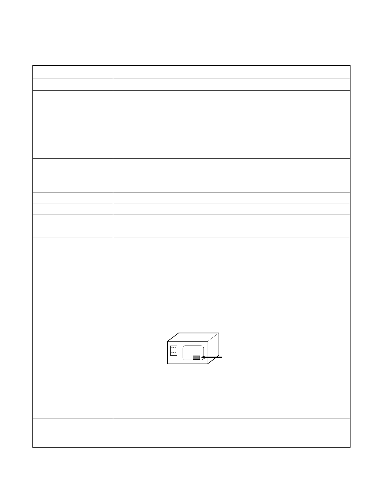
Name Plate Location
ccessories
SPECIFICATIONS
Back side
• DO NOT operate on a 2-wire extension cord during
repair and use.
• NEVER TOUCH any oven components or wiring during
operation.
• BEFORE TOUCHING any parts of the oven, always
remove the power plug from the outlet.
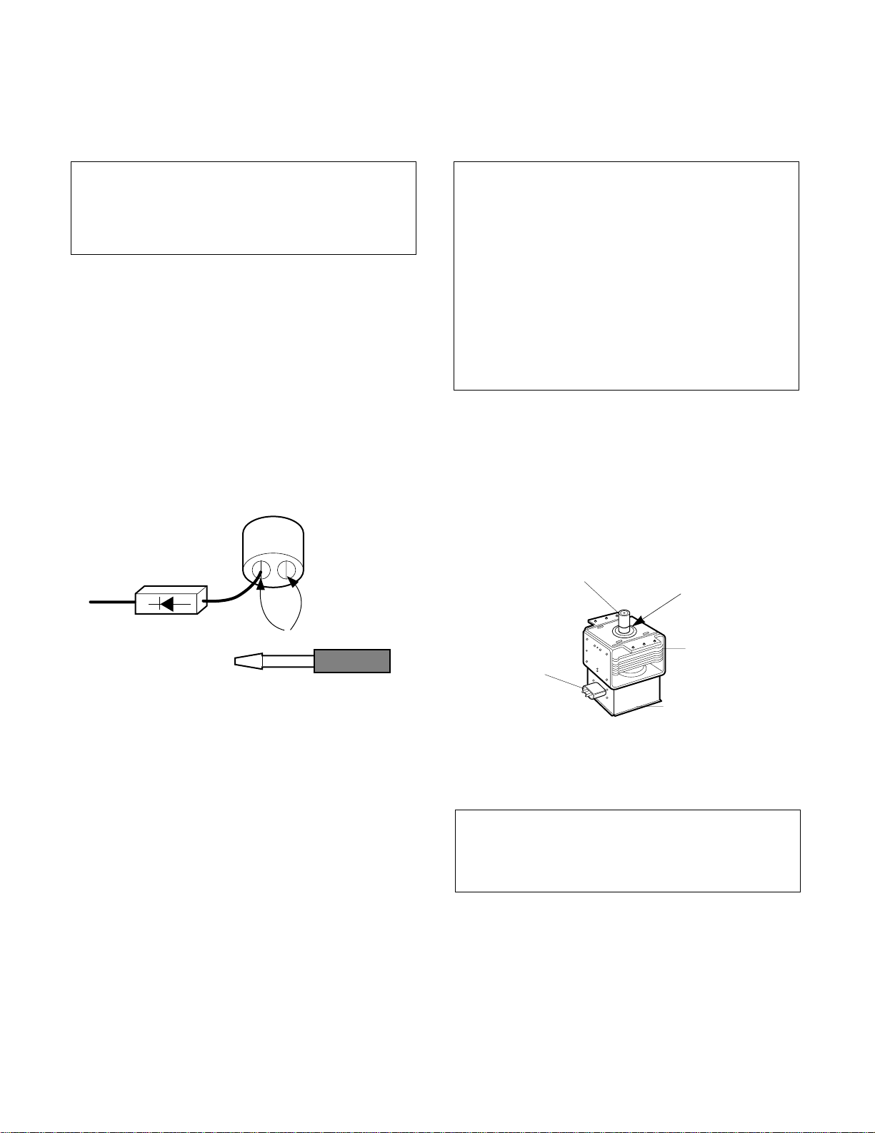
• For about 30 seconds after the oven stops, an electric
charge remains in the high voltage capacitor. When
replacing or checking, you must discharge the high
voltage capacitor by shorting across the two terminals
with an insulated screwdriver.
•
Remove your watches whenever working close to or
replacing the Magnetron.
• NEVER operate the oven with no load.
• NEVER injure the door seal and front plate of the oven
cavity.
• NEVER put iron tools on the magnetron.
• NEVER put anything into the latch hole and the
interlock switches area.
• Proper operation of the microwave oven requires that
the magnetron be assembled to the waveguide and
cavity. Never operate the magnetron unless it is
properly installed.
• B sur that th magn tron gask t is prop rly
install d around th dom of th tub wh n v r
installing th magn tron.
2-1
CAUTIONS
Unlike other appliances, the microwave oven is
high-voltage and high-current equipment.
Though it is free from danger in ordinary use,
extreme care should be taken during repair.
THE OVEN IS TO BE SERVICED ONLY
BY PROPERLY QUALIFIED SERVICE
PERSONNEL.
MICROWAVE RADIATION
Personnel should not be exposed to the
microwave energy which may radiate from the
magnetron or other microwave generating
device if it is improperly used or connection.
ll input and output microwave connections,
waveguide, flange and gasket must be secure
never operate the device without a microwave
energy absorbing load attached.
Never look into an open waveguide or antenna
while the device is energized.
Gask t
NTENN
COOLING FIN
M GNETRON
CH SSIS GROUND
FIL MENT
TERMIN LS
M GNETRON

INSTALLATIONS
3-1
INSTALLING
1. Empty the microwave oven and clean inside it with
a soft, damp cloth. Check for damage such as
misaligned door, damage around the door or dents
inside the cavity or on the exterior.
2. Put the oven on a counter, table, or shelf that is
strong enough to hold the oven and the food and
utensils you put in it. (The control panel side of the
oven is the heavy side. Use care when handling.)
3. Do not block the vent and the air intake openings.
Blocking vent or air intake openings can cause
damage to the oven and poor cooking results.
Make sure the microwave oven legs are in place to
ensure proper air flow.
4. The oven should not be installed in any area where
heat and steam are generated, because they may
damage the electronic or mechanical parts of the
unit.
Do not install the oven next to a conventional
surface unit or above a conventional wall oven.
5. Use microwave oven in an ambient temperature
less than 104°F(40°C).
6. Place the microwave oven on a sturdy and flat
surface at least 10 cm(4 inches) from the wall.
7. Place the microwave oven as far away as possible
from TV, R DIO, COMPUTER, etc., to prevent
interference.
8. Do not touch the front glass during or after cooking
of the Grill and Combination mode.
This glass is very hot during heater operating.
9. Do not operate the oven at microwave and
combination mode with Grill rack placed in the
cavity when the oven is empty.
EARTHING INSTRUCTIONS
This microwave oven is designed to be used in a fully
earthed condition.
It is imperative, therefore, to make sure it is properly
earthed before servicing
W RNING-
THIS PPLI NCE
MUST BE E RTHED
IMPORT NT
s the colors of the wires in the mains lead of this
appliance may not correspond with the colored
markings identifying the terminals in your plug,
proceed as follows.
The wire which is colored gr n-and-y llow must be
connected to the terminal in the plug which is marked
with the letter Eor by the arth symbol ( ) or
colored gr n or gr n-and-y llow.
The wire which is colored blu must be connected to
the terminal in the plug which is marked with the letter
Nor colored black.
The wire which is colored brown must be connected
to the terminal in the plug which is marked with the
letter Lor colored r d.
BEFORE YOU BEGIN, READ THE FOLLOWING INSTRUCTIONS COMPLETELY AND CAREFULLY.
10cm
The wires in this mains lead are colored in
accordance with the following code:
Gr n-and-y llow: Earth
Blu : N utral
Brown: Liv
4-1
OPERATING INSTRUCTIONS
FEATURES
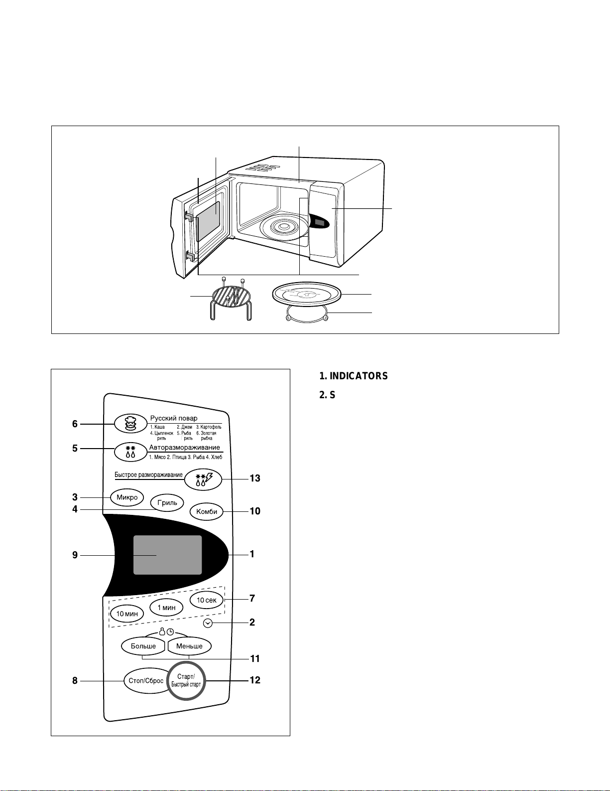
CONTROL PANEL
Oven Front Plate
Door Seal
Control Panel
Safety Door Lock System
Window Door Screen
Grill Rack
Rotating Ring
Turntable
6
5
3
4
7
1
10
13
2
12
11
9
8
1. INDICATORS
2. SET CLOCK: Used to set the time of day.
3. MICRO: Used to select the desired power level
for microwave cooking.
4. GRILL: Used to select the grill cooking.
5. AUTO DEFROST: Used to select the auto weight
defrost.
6. RUSSIAN COOK: Used to cook the foods listed by
one touch.
7. TIME: To set cooking times.
8. STOP/CLEAR: Used to stop oven and clear all
entries except time of day.
CHILD LOCK
9. DISPLAY WINDOW
10. COMBI: Used to select the combination cooking.
11. MORE/LESS: Used to change cooking time.
WEIGHT: Used to select the weight of food.
12. START: One tap allows oven to begin functioning.
13. QUICK DEFROST: Used to defrost quickly.
4-2
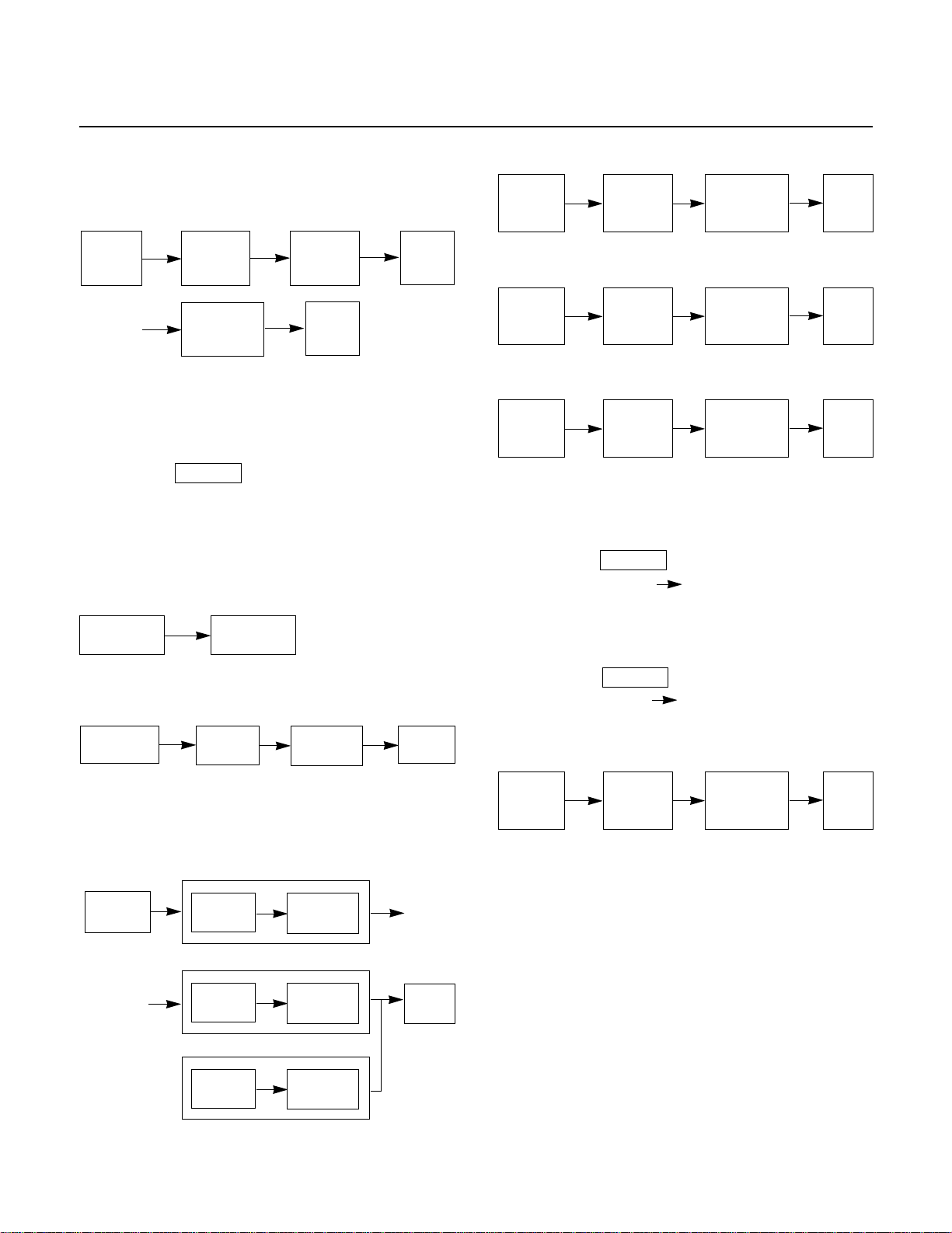
OPERATING SEQUENCE
The following is a description of component functions
during oven operation.
1. SETTING THE CLOCK
NOTE: You can set 12 hour clock or 24 hour clock
optionally.
2. CANCEL FUNCTION
Touch the pad whenever you need to
cancel an entry or a function currently in use.
The display will either return to the last item entered
or to the clock.
3. QUICK START
4. MICROWAVE COOKING
5. MULTI-STAGE MICROWAVE
COOKING
6. GRILL COOKING
7. COMBINATION COOKING
8. AUTO WEIGHT EFROST
9. CHIL LOCK
This oven has a CHILD LOCK feature
• TO SET CHILD LOCK
• Touch the pad
• Touch STOP pad L appear in
the display.
•TO C NCEL CHILD LOCK
• Touch the pad
• Touch STOP pad L disappears.
10. RUSSIAN COOK
Stop Set
clock Set the
correct hour
Set the
correct minute
Stop Start
STOP
ST GE 1
Touch
start
Stop
Start
Stop Grill
Desired
cooking Time
Start
Stop
Desired
combi
category Desired
cooking Time
Start
Stop
Desired
defrost
category
Desired
cooking
Weight
Start
Stop
Desired
russian cook
category
Desired
cooking
Weight
Start
Touch
start
Stop Desired
power level Desired
cooking time Start
ST GE 2
Stop
Stop
Desired
power level Desired
cooking time
Desired
power level Desired
cooking time
Grill
or Combi Desired
cooking time
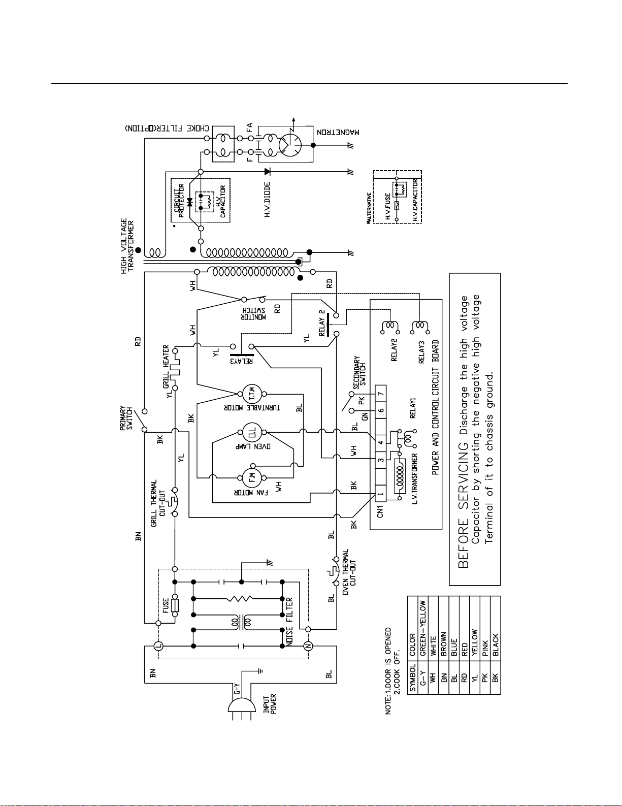
SCHEMATIC DIAGRAM
4-3
CIRCUIT DESCRIPTION
GENERAL ETAILS
• The low voltage transformer supplies the necessary
voltage to the micom controller when power cord is
plugged in.
• When the door is closed, the primary switch is ON, the
secondary switch is ON, and the monitor switch opens
(contact COM and NO).
WHEN SELECTING COOKING POWER
LEVEL AN TIME
• The micom controller memorizes the function you set.
• The time you set appears in the display window.
• Each indicator light turns on to indicate that the stage
has been set.
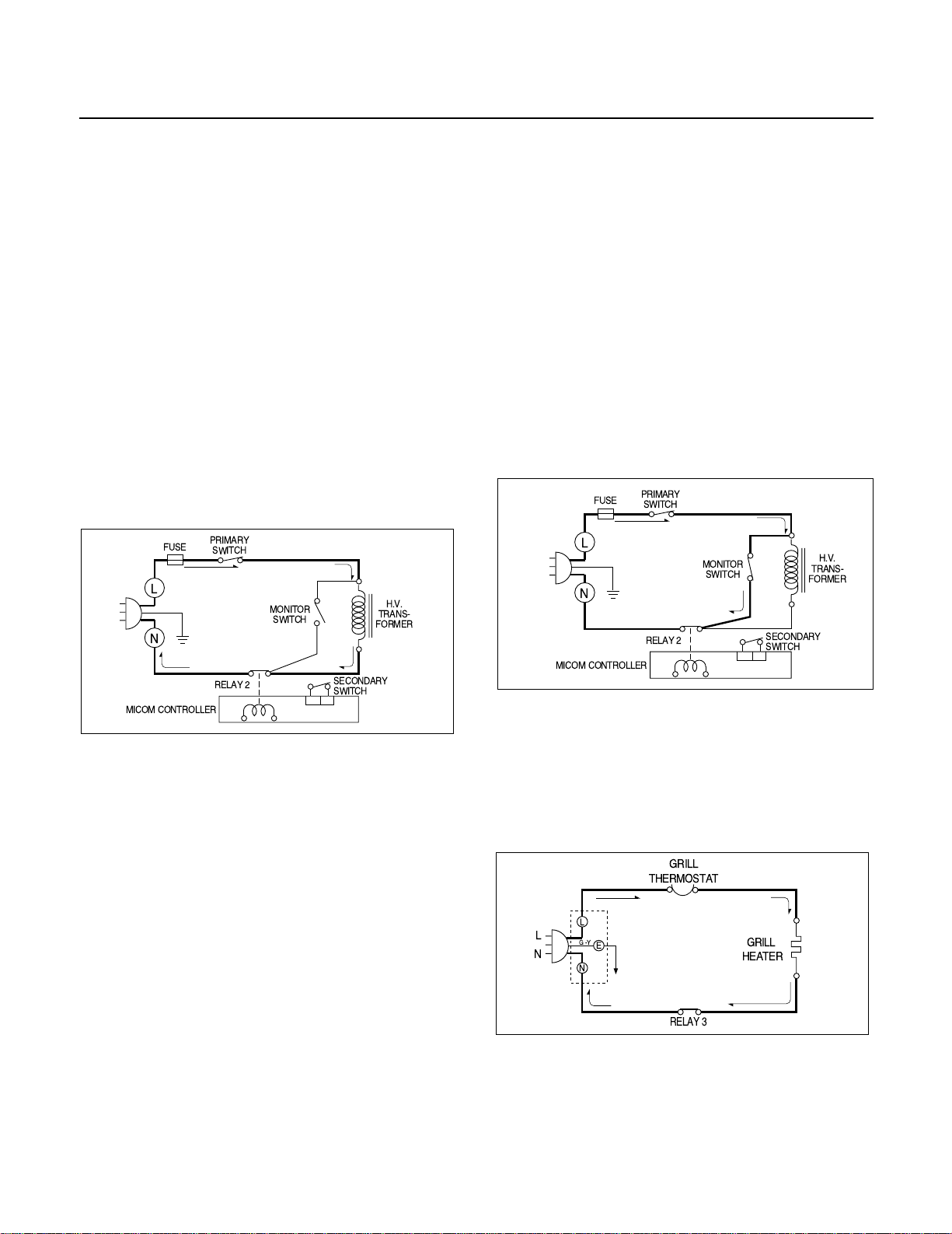
WHEN TOUCHING THE START PA
• The coil of the relay is energized by the micom
controller.
• Power input is supplied to the high voltage transformer
through the fuse to the primary switch and relay 2.
• Turntable rotates.
• The fan motor rotates and cools the magnetron by
blowing the air (coming from the intake on the
baseplate).
• The air is also directed into the oven to exhaust the
vapor in the oven through the upper plate.
• Cooking time starts counting down.
• 3.2 volts C is generated from the filament winding of
the high voltage transformer. This 3.2 volts is applied to
the magnetron to heat the magnetron filament through
two noise-preventing choke coils.
• high voltage of approximately 2100 volts C is
generated in the secondary of the high voltage
transformer which is increased by the action of the high
voltage diode and charging of the high voltage
capacitor.
• The negative 4,000 Volts DC is applied to the filament
of the magnetron.
WHEN THE OVEN IS SET AT ANY LEVEL
EXCEPT MAXIMUM.
• The micom controller controls the ON-OFF time of
relay 2 by the applied signal to vary the average output
power of microwave oven as POWER LEVEL.
(refer to page 1-1)
WHEN THE OOR IS OPENE URING
COOKING
• Both the primary switch and relay 2 are cut off primary
winding voltage of the high voltage transformer.
• ON-OFF of relay 2 is coupled electrically with opening
and closing of the secondary switch.
• When the door is opened, the secondary switch is
opened and when the door is closed, the secondary
switch is closed.
• The cooking time stops counting down.
• Relay stops functioning.
• s the door is opened, if the contact of primary switch
and relay 2 and/or secondary switch fails to open, the
fuse opens due to the large current surge caused by
the monitor switch activation, which in turn stops
magnetron oscillation.
WHEN TOUCHING THE START KEY
WITH THE GRILL COOKING FUNCTION
SELECTE
• The contacts of the primary switch and the secondary
switch close the circuit.
• .C. voltage is applied to the grill heater through grill
thermostat as shown by the solid line.
• Turntable rotates.
• The fan motor rotates.
• The air is also directed into the oven to exhaust the
vapor in the oven through the base plate and upper
plate.
4-4
L
FUSE
H.V.
TRANS-
FORMER
RELAY 2
MICOM CONTROLLER
SECONDARY
SWITCH
PRIMARY
SWITCH
N
MONITOR
SWITCH
MONITOR
SWITCH
L
FUSE
H.V.
TRANS-
FORMER
RELAY 2
MICOM CONTROLLER
SECONDARY
SWITCH
PRIMARY
SWITCH
N
RELAY 3
L
N
GRILL
THERMOSTAT
GRILL
HEATER
L
G-Y
N
E
This manual suits for next models
1
Table of contents
Other LG Microwave Oven manuals


M Service manual")


