LG PVDSMN000 Operating instructions

P/NO : MFL67888701
INSTALLATION/
OWNER’S MANUAL
IO Module(Multi-V IV)
AIR
CONDITIONER
www.lg.com
Please read this manual carefully before operating
your set and retain it for future reference.
ENGLISH ITALIANO ESPAÑOL FRANCAIS DEUTSCH
PORTUGUÊS
TÜRKÇE
РУССКИЙ ЯЗЫК

2TIPS FOR SAVING ENERGY
ENGLISH
TIPS FOR SAVING ENERGY
Here are some tips that will help you minimize the power consumption when you use the air
conditioner. You can use your air conditioner more efficiently by referring to the instructions
below:
• Do not cool excessively indoors. This may be harmful for your health and may consume more
electricity.
• Block sunlight with blinds or curtains while you are operating the air conditioner.
• Keep doors or windows closed tightly while you are operating the air conditioner.
• Adjust the direction of the air flow vertically or horizontally to circulate indoor air.
• Speed up the fan to cool or warm indoor air quickly, in a short period of time.
• Open windows regularly for ventilation as the indoor air quality may deteriorate if the air con-
ditioner is used for many hours.
• Clean the air filter once every 2 weeks. Dust and impurities collected in the air filter may block
the air flow or weaken the cooling / dehumidifying functions.
For your records
Staple your receipt to this page in case you need it to prove the date of purchase or for warranty
purposes. Write the model number and the serial number here:
Model number :
Serial number :
You can find them on a label on the side of each unit.
Dealer’s name :
Date of purchase :

IMPORTANT SAFETY INSTRUCTIONS
ENGLISH
IMPORTANT SAFETY INSTRUCTIONS
READ ALL INSTRUCTIONS BEFORE USING THE APPLIANCE.
Always comply with the following precautions to avoid dangerous situations and ensure peak
performance of your product
WARNING
It can result in serious injury or death when the directions are ignored
CAUTION
It can result in minor injury or product damage when the directions are ignored
WARNING
• Installation or repairs made by unqualified persons can result in hazards to you and others.
• Installation work must be performed in accordance with the National Electric Code by quali-
fied and authorized personnel only.
• The information contained in the manual is intended for use by a qualified service technician
familiar with safety procedures and equipped with the proper tools and test instruments.
• Failure to carefully read and follow all instructions in this manual can result in equipment mal-
function, property damage, personal injury and/or death.
WARNING
Installation
• Be sure to request to the service center or installation specialty store when installing products.
It will cause fire or electric shock or explosion or injury.
•
Request to the service center or installation specialty store when reinstalling the installed product.
It will cause fire or electric shock or explosion or injury.
• Do not disassemble, fix, and modify products randomly.
It will cause fire or electric shock.
• Be sure to turn off outdoor unit power before installation.
It will cause electric shock.
• Installation work must be performed in accordance with the national wiring standards by au-
thorized personnel only.
In-use
• Do not place flammable stuffs close to the product.
It will cause fire.
• Do not allow water to run into the product.
It will cause electric shock or breakdown.
• Do not give the shock to the product.
It will cause breakdown when giving the shock to the product.
• Request to the service center or installation specialty store when the product becomes wet.
It will cause fire or electric shock.
• Do not give the shock using sharp and pointed objects.
It will cause breakdown by damaging parts.
!
!
!
!
3

4IMPORTANT SAFETY INSTRUCTIONS
ENGLISH
CAUTION
In-use
• Do not clean using the powerful detergent like solvent but use soft cloths.
It will cause fire or product deformation.
• Do not press the screen using powerful pressure or select two buttons.
It will cause product breakdown or malfunction.
• Do not touch or pull the lead wire with wet hands.
It will cause product breakdown or electric shock.
!
ENGLISH Disposal of your old appliance
1. When this crossed-out wheeled bin symbol is attached to a product it means the product is cov-
ered by the European Directive 2002/96/EC.
2. All electrical and electronic products should be disposed of separately from the municipal waste
stream via designated collection facilitiesappointed by the government or the local authorities.
3. The correct disposal of your old appliance will help prevent potential negative consequences for
the environment and human health.
4. For more detailed information about disposal of your old appliance, please contact your city office,
waste disposal service or the shop where you purchased the product.

TABLE OF CONTENTS
ENGLISH
5
TABLE OF CONTENTS
2TIPS FOR SAVING
ENERGY
3IMPORTANT SAFETY
INSTRUCTIONS
6COMPONENTS
7NAME OF EACH PART
8INSTALLATION METHOD
10 SETTING AND USING
METHOD
10 Setting
15 Wiring
16 Using

6COMPONENTS
ENGLISH
COMPONENTS
IO Module Cable
4 Screws (10mm*2ea, 12mm*2ea)Manual
Bracket Clamp,Cord
(105mm*2ea)

NAME OF EACH PART
ENGLISH
7
NAME OF EACH PART
ڸ
ڹ
ڼڽ
ۀ
ڿ
ں
ھ
ڻ
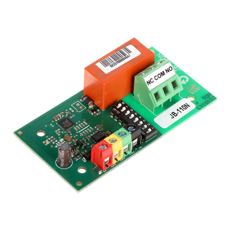
①Main connector : Power input and communication connector with Outdoor unit
②SW102 : Switch for setting internal function
③SW104 : Rotary Switch for setting Demand control step
④Digital Output : Operating & Error status Relay output (250V, 1A)
Reserved Relay output (250V, 1A)
⑤Digital Input : Dry contact input
⑥Analog Input : DC 0 ~ 10 V Analog signal input
⑦Analog Output : DC 0 ~ 10 V Analog signal output
⑧SW103 : Reset Switch
⑨SW101 : Dip Switch for setting operating function

8INSTALLATION METHOD
ENGLISH
①Separate front panel from outdoor unit.
②Separate front cover of control box.
③Assemble IO Module and bracket.
④Fix the bracket on designated location with two clamp cords(105mm).
⑤
Connect the connection wires according to the instructions. (Please refer to Setting and Using Method)
CAUTION
Be sure to turn off outdoor unit power before installation.
!
ڸ
ڹ
ںڻ
++
UX3
INSTALLATION METHOD
ڼ
Main board connector

INSTALLATION METHOD
ENGLISH
9
⑥Fix and fasten components and cables.
⑦Perform the switch setting according to the instructions.
Using 105mm clamp cords, fasten the core as below.
Using 65mm clamp cords, fasten the relay output cable as below.

10 SETTING AND USING METHOD
ENGLISH
SETTING AND USING METHOD
Setting
Setting of Dip Switch
Using ‘SW101’, select the option of control function as described below.
L1
ON
234
NOTE
!
Default status is all off
Position Function
ON
L1 2 3 4
ON : Enable Low Noise Operation
OFF : Disable Low Noise Operation
Position Function
ON
L1 2 3 4
ON : Activate Digital Output according to Indoor Unit status
OFF : Activate Digital Output according to Outdoor Unit status
• L3 : Set Low Noise Operation
This is a function driving outdoor unit fan RPM to operate low speed for reducing fan noise ac-
cording to the input signal. To use this function, you should set Outdoor unit mode, Please refer
to PDB more detail.
• L4 : Set Operating status output
CAUTION
After change Dip SW setting, press reset switch to reflect the setting.
!
CAUTION
If the Dip SW is set , IO module System is operating preferentially than outdoor unit setting.
!
Table of contents