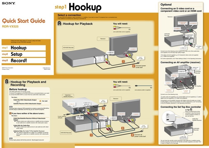
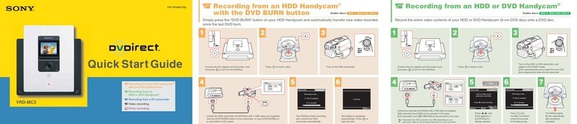
LG DR7400 User manual

SERVICE MANUAL
LG DR-7400
MODEL

CONTENTS
SECTION 1 . . . . SUMMARY
SECTION 2 . . . . CABINET & MAIN CHASSIS
SECTION 3 . . . . ELECTRICAL
SECTION 4 . . . . REPLACEMENT PARTS LIST

1-1
SECTION 1
SUMMARY
CONTENTS
PRODUCT SAFETY SERVICING GUIDELINES FOR VIDEO PRODUCTS.............. 1-2
SERVICING PRECAUTIONS .................................................................................................. 1-3
• Gene al Se vicing P ecautions
• Insulation Checking P odedu e
• Elect ostatically Sensitive Devices
SERVICE INFORMATION FOR EEPROM IC SETTING.................................................. 1-4
SPECIFICATIONS ...................................................................................................................... 1-5

1-21-2
IMPORTANT SAFETY NOTICE
This manual was prepared for use only by properly trained audio-video service
technicians.
When servicing this product, under no circumstances should the original
design be modified or altered without permission from LG Electronics
Corporation. ll components should be replaced only with types identical to
those in the original circuit and their physical location, wiring and lead dress
must conform to original layout upon completion of repairs.
Special components are also used to prevent x-radiation, shock and fire haz-
ard. These components are indicated by the letter “x” included in their compo-
nent designators and are required to maintain safe performance. No deviations
are allowed without prior approval by LG Electronics Corporation.
Circuit diagrams may occasionally differ from the actual circuit used. This way,
implementation of the latest safety and performance improvement changes
into the set is not delayed until the new service literature is printed.
CAUTION: Do not attempt to modify this product in any way. Never perform
customized installations without manufacturer’s approval. Unauthorized modi-
fications will not only void the warranty, but may lead to property damage or
user injury.
Service work should be performed only after you are thoroughly familiar with
these safety checks and servicing guidelines.
GRAPHIC SYMBOLS
The exclamation point within an equilateral triangle is intended to
alert the service personnel to important safety information in the
service literature.
The lightning flash with arrowhead symbol within an equilateral
triangle is intended to alert the service personnel to the presence
of noninsulated “dangerous voltage” that may be of sufficient
magnitude to constitute a risk of electric shock.
The pictorial representation of a fuse and its rating within an equi-
lateral triangle is intended to convey to the service personnel the
following fuse replacement caution notice:
CAUTION: FOR CONTINUED PROTECTION G INST RISK
OF FIRE, REPL CE LL FUSES WITH THE S ME TYPE ND
R TING S M RKED NE R E CH FUSE.
SERVICE INFORMATION
While servicing, use an isolation transformer for protection from C line shock.
fter the original service problem has been corrected, make a check of the fol-
lowing:
FIRE AND SHOCK HAZARD
1. Be sure that all components are positioned to avoid a possibility of adjacent
component shorts. This is especially important on items trans-ported to and
from the repair shop.
2. Verify that all protective devices such as insulators, barriers, covers, shields,
strain reliefs, power supply cords, and other hardware have been reinstalled
per the original design. Be sure that the safety purpose of the polarized line
plug has not been defeated.
3. Soldering must be inspected to discover possible cold solder joints, solder
splashes, or sharp solder points. Be certain to remove all loose foreign par-
ticles.
4. Check for physical evidence of damage or deterioration to parts and compo-
nents, for frayed leads or damaged insulation (including the C cord), and
replace if necessary.
5. No lead or component should touch a high current device or a resistor rated
at 1 watt or more. Lead tension around protruding metal surfaces must be
avoided.
6. fter reassembly of the set, always perform an C leakage test on all
exposed metallic parts of the cabinet (the channel selector knobs, antenna
terminals, handle and screws) to be sure that set is safe to operate without
danger of electrical shock. DO NOT USE LINE ISOL TION TR NS-
FORMER DURING THIS TEST. Use an C voltmeter having 5000 ohms per
volt or more sensitivity in the following manner: Connect a 1500 ohm, 10
watt resistor, paralleled by a .15 mfd 150V C type capacitor between a
known good earth ground water pipe, conduit, etc.) and the exposed metal-
lic parts, one at a time. Measure the C voltage across the combination of
1500 ohm resistor and .15 mfd capacitor. Reverse the C plug by using a
non-polarized adaptor and repeat C voltage measurements for each
exposed metallic part. Voltage measured must not exceed 0.75 volts RMS.
This corresponds to 0.5 milliamp C. ny value exceeding this limit consti-
tutes a potential shock hazard and must be corrected immediately.
TIPS ON PROPER INSTALLATION
1. Never install any receiver in a closed-in recess, cubbyhole, or closely fitting
shelf space over, or close to, a heat duct, or in the path of heated air flow.
2. void conditions of high humidity such as: outdoor patio installations where
dew is a factor, near steam radiators where steam leakage is a factor, etc.
3. void placement where draperies may obstruct venting. The customer
should also avoid the use of decorative scarves or other coverings that
might obstruct ventilation.
4. Wall- and shelf-mounted installations using a commercial mounting kit must
follow the factory-approved mounting instructions. product mounted to a
shelf or platform must retain its original feet (or the equivalent thickness in
spacers) to provide adequate air flow across the bottom. Bolts or screws
used for fasteners must not touch any parts or wiring. Perform leakage tests
on customized installations.
5. Caution customers against mounting a product on a sloping shelf or in a tilt-
ed position, unless the receiver is properly secured.
6. product on a roll-about cart should be stable in its mounting to the cart.
Caution the customer on the hazards of trying to roll a cart with small cast-
ers across thresholds or deep pile carpets.
7. Caution customers against using extension cords. Explain that a forest of
extensions, sprouting from a single outlet, can lead to disastrous conse-
quences to home and family.
.C. Voltmeter
1500 OHM
10 W TT
Place this probe
on each exposed
metal part.
Good Earth Ground
such as the Water
Pipe, Conduit, etc.
0.15uF
PRODUCT SAFETY SERVICING GUIDELINES FOR VIDEO PRODUCTS

1-3
SERVICING PRECAUTIONS
C UTION : Before servicing the DVD Recorder covered by
this service data and its supplements and addends, read and
follow the SAFETY PRECAUTIONS. NOTE : if unforeseen
circumstances create conflict between the following servic-
ing precautions and any of the safety precautions in this pub-
lications, always follow the safety precautions.
Remembers Safety First:
Gene al Se vicing P ecautions
1. lways unplug the DVD Recorder C power cord from the
C power source before:
(1) Removing or reinstalling any component, circuit board,
module, or any other assembly.
(2) Disconnection or reconnecting any internal electrical
plug or other electrical connection.
(3) Connecting a test substitute in parallel with an elec-
trolytic capacitor.
Caution : wrong part substitution or incorrect
polarity installation of electrolytic capacitors may result
in an explosion hazard.
2. Do not spray chemicals on or near this DVD Recorder or
any of its assemblies.
3. Unless specified otherwise in this service data, clean
electrical contacts by applying an appropriate contact
cleaning solution to the contacts with a pipe cleaner,
cotton-tipped swab, or comparable soft applicator.
Unless specified otherwise in this service data, lubrication
of contacts is not required.
4. Do not defeat any plug/socket B+ voltage interlocks with
whitch instruments covered by this service manual might
be equipped.
5. Do not apply C power to this DVD Recorder and/or any
of its electrical assemblies unless all solid-state device
heat sinks are cerrectly installed.
6. lways connect test instrument ground lead to the
appropriate ground before connection the test instrument
positive lead. lways remove the test instrument ground
lead last.
Insulation Checking P ocedu e
Disconnect the attachment plug from the C outlet and turn
the power on. Connect an insulation resistance meter(500V)
to the blades of the attachment plug. The insulation resis-
tance between each blade of the attachment plug and acces-
sible conductive parts (Note 1) should be more than 1M-
ohm.
Note 1 : ccessible Conductive Parts including Metal pan-
els, Input terminals, Earphone jacks, etc.
Elect ostatically Sensitive (ES) Devices
Some semiconductor (solid state) devices can be damaged
easily by static electricity. Such components commonly are
called Electrostatically Sensitive (ES) Devices. Examples of
typical ES devices are integrated circuits and some field
effect transistors and semiconductor chip components.
The following techniques should be used to help reduce the
incidence of component damage caused by static electricity.
1. Immediately before handling any semiconductor compo-
nent or semiconductor-equipped assembly, drain off any
electrostatic charge on your body by touching a known
earth ground. lternatively, obtain and wear a commer-
cially available discharging wrist strap device, which
should be removed for potential shock reasons prior to
applying power to the unit under test.
2. fter removing an electrical assembly equipped with ES
devices, place the assembly on a conductive surface such
as aluminum foil, to prevent electrostatic charge buildup or
exposure of the assembly.
3. Use only a grouned-tip soldering iron to solder or unsolder
ES devices.
4. Use only an anti-static solder removal device. Some
solder removal devices not classified a “anti-static” can
generate electrical charges sufficient to damage ES
devices.
5. Do not use freon-propelled chemicals. These can
generate electrical charge sufficient to damage ES
devices.
6. Do not remove a replacement ES device from its protec
tive package until immediately before you are ready to
install it. (Most replacement ES devices are packaged with
leads electrically shorted together by conductive foam,
aluminum foil, or comparable conductive material).
7. Immediately before removing the protective material from
the leads of a replacement ES device, touch the protective
material to the chassis or circuit assembly into which the
device will be installed.
Caution : Be sure no power is applied to the chassis or
circuit, and observe all other safety precautions.
8. Minimize bodily motions when handling unpackaged
replacement ES devices. (Normally harmless motion such
as the brushing together of your clothes fabric or the lifting
of your foot from a carpeted floor can generate static elec-
tricity sufficient to damage an ES device.)

1-5
SPECIFICATIONS
• GENERAL
Power requirements C 110-240V, 50/60 Hz
Power consumption 30W
Dimensions (approx.) 430x69x280 mm (w x h x d)
Mass (approx.) 3.8 Kg
Operating temperature 5°C to 35°C
Operating humidity 5 % to 90 %
Television system P L B/G colour system
Recording format P L
• RECORDING
Recording format DVD Video Recording, DVD-VIDEO
Recordable discs DVD+ReWritable, DVD+Recordable
Recordable time pprox. 1 hour (HQ mode), 2 hours (SQ mode),
4 hours (LQ mode), 6 hours (EQ mode)
Video eco ding fo mat
Sampling frequency 27MHz
Compression format MPEG 2
Audio eco ding fo mat
Sampling frequency 48kHz
Compression format Dolby Digital
• PLAYBACK
Frequency response DVD (PCM 48 kHz): 8 Hz to 22 kHz, CD: 8 Hz to 20 kHz
DVD (PCM 96 kHz): 8 Hz to 44 kHz
Signal-to-noise ratio More than 100 dB ( UDIO OUT connector)
Harmonic distortion Less than 0.008% THD ( UDIO OUT connector)
Dynamic range More than 95 dB ( UDIO OUT connector)
• INPUTS
NTENN IN ntenna input, 75 ohms
VIDEO IN 1.0 Vp-p 75 ohms, sync negative, RC Jack x 1, SC RT x 2
UDIO IN 0 dBm more than 47 kohms, RC Jack x 1, SC RT x 2
SUPER IN (Y)1.0V(p-p), 75Ω, negative sync, Mini DIN 4-pin x 1
(C) 0.3V(p-p), 75Ω
• OUTPUTS
VIDEO OUT 1 Vp-p 75 Ω, sync negative, RC jack x 1
udio output (digital audio) 0.5 V (p-p), 75 Ω, RC jack x 1
udio output (analog audio) 2.0 Vrms (1 KHz, 0 dB), 600 Ω/SC RT

2-1
SECTION 2
CABINET & MAIN CHASSIS
CONTENTS
EXPLODED VIEWS ....................................................................................................................2-2
1. Cabinet and Main F ame Section ...........................................................................................2-2
2. Deck Mechanism Section(DR-06 + MAIN PCB).....................................................................2-3
3. Packing Accesso y Section....................................................................................................2-4

2-2
EXPLODED VIEWS
1. Cabinet and Main F ame Section
275
275
452
452
280
255
274
463
463
468
300
465
250
272
260
261
465
465
261
261
261
320 265
468
463
463
463
463
283
452
A50
A43
A48
A44
A47
A60
A52
A000
277
262
TU701
OPTIONAL
PART
A
5
4
3
2
1
BCD

2-3
2. DECK MECHANISM SECTION(DR-06 + MAIN PCB)
1001
A001
1025
1025
1030
1432
1029
1432
1021
1432
1432
1032
1033
1011
1019
1009
1020
1019
1012
1013
1439
1014
1016
1015
1017
1018
1018A
1018B
1018E
1435
1018E
1018D
1006
1436
1024
1433
1029
1027
1027
1026
1003 1002
A004
A002
A000
A60
1437
1005
1434
1434
MAIN PCB

2-4
808 Battery
Cable, Coaxial
Plug Ass'y, 1Way
Plug Ass'y, 2Way
Bag
Packing
Remote Control
Instruction Ass'y
Packing
Box
806
804
803
811
812
FLAT CABLE
822
801
900
802
803
810 CABLE ASS'Y 821 SCART CABLE
OPTIONAL PART
3. Packing Accesso y Section
Other manuals for DR7400
1
Table of contents
Other LG DVD Recorder manuals