
LARSON MT-BBT-208V-230V-20.8A User manual

MT-BBT-208V-230V-20.8A
1-Phase Buck/Boost Step-Up Transformer - 208V Primary - 230V Secondary - 18.6 Amps -
50/60Hz
Product ID: 271912
Larson Electronics LLC manufactures a wide variety of products, including custom built to spec designs.
The pictures displayed for this unit are a general representation of form factor for the product line and
may not accurately represent this exact configuration in every detail due to custom builds and changes
between similar products in our standard catalog. The specifics for this configuration are listed in the
specification table and supporting documentation (CAD files, Dimensional Drawing, Name Plate Diagram,
Wiring Diagram, etc.). This means that specific details (receptacles, plugs, wires, connections, mounting
brackets, external finishes, etc.) may not be accurately represented in images vs specifications. Please
review specifications and do not order based solely on images.
MT-BBT-208V-230V-20.8A Buck and Boost Step-Up Transformer Ratings
Transformer Type: Buck/Boost step-up Autotransformer NRTL Listed for United States
Transformer Configuration: Boost (increase) NRTL Certified for Canada
Phase: Single Phase NEMA 3R Indoor/Outdoor Enclosure
Frequency: 50/60 Hz Meets or Exceeds NEMA ST-20 Standards
Input Voltage: 208 V AC Buck and Boost Step-Up Transformer
Primary Amps: 20 A @ 208 V
Primary Configuration: Two winding
kVA: 4.77
Output Voltage: 230 V AC
Secondary Amps: 18.6 A @ 230 V
Voltage Difference: 22 V
Voltage % Difference: 90%
Secondary Configuration: Two winding
Winding Material: Aluminum
Knockouts: Side and rear
Wiring Termination: Front access (8) Lead Wires
Cooling: Air / Dry Type
Insulation: 130°C
Temperature Rise: 80°C
Sound Level: 36 dB
Enclosure Rating: NEMA 3R
Encapsulation: Silica sand, resin compounds
Enclosure Material: Steel
Finish: ANSI 61 Grey Special Orders - Requirements
Mounting: Wall mount via mounting tabs Contact us for special requirements
Dimensions: 9.30"H x 5.06"W x 4.56"D Toll Free: 1-800-369-6671
1
Larson Electronics LLC
9419 E US HWY 175, Kemp, TX 75143
Phone: 800.369.6671
www.LarsonElectronics.com
Email: [email protected]
Fax: 903.498.3364

Weight: 15 lb Intl: 1-214-616-6180
The MT-BBT-208V-230V-20.8A single phase step-up Buck and Boost
Transformer from Larson Electronics is powerful, reliable, and designed
with the environment in mind. This transformer is designed to increase
208 volts to 230 volts, and is needed when the line-voltage is lower than
the required voltage for equipment. Suitable for both indoor and outdoor
applications, the MT-BBT-208V-230V-20.8A provides increased reliability,
higher efficiency, protection against critical equipment failures and an
extra level of protection by isolating the power source from the connected
device. The lower operating costs, lower heat emissions and lower cost of
ownership make this transformer ideal for a wide range of applications
and businesses.
*PLEASE NOTE: ANY FREE SHIPPING OFFERS DO NOT APPLY TO POWER
DISTRIBUTION PANELS, TRANSFORMERS, OR SUBSTATIONS*
Transformer Features: The MT-BBT-208V-230V-20.8A buck and boost
transformer is a single phase unit with a 4.77 KVA rating and a primary voltage of
208 VAC using a maximum of 20 amps on the primary side. This step-up
transformer has a secondary voltage of 230 V and provides up to 18.6 amps
available on the secondary side. Featuring robust construction, this unit`s cores
are manufactured with non-aging, cold-rolled silicon steel laminations using state
of the art technology.
The MT-BBT-208V-230V-20.8A is designed to increase voltage from an input
voltage of 208 volts to an output voltage of 230 volts. The increase of voltage is
necessary when the on-site line-voltage is consistently lower than the voltage
required by the equipment being operated or installed, preserving the lifespan of
the equipment and guarantees correct operation without risking damage due to
incorrect voltage. This step-up transformer will allow equipment that draws up to
18.6 amps at 230 to be powered from 208 volt power sources. Situations for this
type of transformer may include lower voltage from your electrical provider or
within the existing establishment, or operating equipment that requires a lower
voltage than is provided at the existing establishment.
This unit boasts a low cost of ownership and is highly energy efficient. Lower heat
emissions mean less cooling is needed as well. The NEMA 3R painted steel
enclosure makes the unit suitable for both indoor and outdoor applications. This
step-up transformer can be either floor or wall mounted. The MT-BBT-208V-230V-
20.8A features a 130°C insulation with a 80°C temperature rise.
Construction: The aluminum winding in the MT-BBT-208V-230V-20.8A are
formed from high quality aluminum wire helps to improve performance. The close
tolerances used during manufacturing also eliminate burrs which hinder
performance. Each core is specially coated to prevent the ingress of moisture and
are electrically balanced to minimize axial forces during short circuit situations.
Buck and boost transformers are designed to maximize the performance and life
of electrical equipment. The MT-BBT-208V-230V-20.8A is encapsulated in silica
sand and resin, and cased in a NEMA 3R steel enclosure. NEMA 4, NEMA 4X, and
NEMA 12 enclosures are available upon request.
Click Image to Enlarge
Benefits: The MT-BBT-208V-230V-20.8A buck/boost step-up transformer offers
many benefits to the consumer. Buck/boost transformers pass the majority of the
load voltage directly through the transformer, only transforming a small
percentage of the load. Due to this technology, a smaller and quieter step-up
2
Larson Electronics LLC
9419 E US HWY 175, Kemp, TX 75143
Phone: 800.369.6671
www.LarsonElectronics.com
Email: [email protected]
Fax: 903.498.3364

transformer is manufactured and uses less material. This provides owners with
significant energy savings as well as offering environmental benefits.
Higher efficiency extends the life of the transformer and turn into cost savings for
owners in the form of lower energy bills and a decrease cost of ownership when
compared to large autotransformers. Installation and maintenance costs are
reduced due to the smaller form factor, and less overall space requirements are
decreased. In addition, these step-up transformers operate quieter than a
standard autotransformer of the same capacity.
Mounting: Integrated wall mounting brackets make installation fast and easy.
Because of the smaller overall footprint, heavy machinery is rarely needed for
mounting and installation.
Installation: Installation is simple. Connect the primary leads and secondary
leads to the step-up transformer per the provided wiring diagram. Knockout hubs
on both side and the bottom of the transformer allow for easy line-in and line-out
wiring. The front access cover provides convenient access to the eight lead wires.
The MT-BBT-208V-230V-20.8A is shipped with the necessary wire nuts for wiring
this step-up transformer in-line between line voltage and equipment.
Applications: Air conditioners, lighting systems, heating elements, motor
applications and other applications that require the ability to power loads that
differ from the available line voltage.
Limitations: While there are many benefits to a buck/boost transformer, there
are some limitations to consider. This transformer will only transformer voltage, it
will not convert phases, it will not create even legs between line 1 and line 2 (L1
and L2 WILL be UNEVEN), has no circuit isolation, and does not create a neutral
for applications where a neutral is not already present. If any of these limitations
apply to you, you will need a standard transformer. Please see below link for our
standard line of industrial transformers or our line of phase converters.
Note on Phases: This buck/boost transformer is a single phase step-up
transformers. For three phase transformers, click on the following links:
Three Phase Delta Buck/Boost Transformers
Three Phase Wye Buck/Boost Transformers
Larson Electronics is a manufacturer and as such can build stationary and portable
transformer systems to your specifications. Although we carry several models of
power distribution transformer systems, we can deliver custom ordered units
almost as quickly as our prebuilt units. If this model does not meet your needs,
please contact us at 1-800-369-6671 or [email protected] to discuss
your specific requirements.
3
Larson Electronics LLC
9419 E US HWY 175, Kemp, TX 75143
Phone: 800.369.6671
www.LarsonElectronics.com
Email: [email protected]
Fax: 903.498.3364

Larson Electronics, LLC Phone: (800) 369-6671 Fax: (903) 498-3364 www.larsonelectronics.com
1of 7
DIAGRAM D
BUCK & BOOST TRANSFORMERS
SINGLE PHASE BUCK & BOOST TRANSFORMERS
INSTRUCTION MANUAL
This manual applies to all single-phase buck & boost transformers sold by Larson Electronics. Please refer to
the connection diagram on pages 4-6 for properly connecting the transformer.
Warning: Do not attempt installation until you are familiar with all warnings, precautions, and procedures
outlined within this instruction sheet. We strongly encourage only a licensed electrician install, operate and
maintain this product.
Precautions:
•Do not handle this transformer without proper equipment and experienced personnel.
•Fully inspect the transformer before installation.
•Use appropriate electrical terminals with flexible connectors.
•Connections should be in accordance with nameplate drawings or attached wiring diagrams.
•Disconnect all live power before installing and maintaining the transformer.
•Do not change any connections while the transformer is energized.
•Secure all ground connections before energizing the transformer.
After receiving the transformer, immediately inspect each unit for damage that could have resulted from transit.
Check to ensure the specs on the transformer match the shipping documents. A claim should be filed with the
carrier if any shipping damage is noted. These details with all relevant information should also be forwarded to
Larson Electronics.
Use appropriate measures and experienced personnel for transporting the transformer relative to its size.
Never attempt to lift the transformer without proper equipment. Lifting tabs are included on larger transformers
to help ease transportation.
All MT-BBT Buck-Boost transformers are NEMA 3R rated, suitable for both indoor and outdoor installations.
Follow appropriate electrical codes for cable installation and use suitable hardware for outdoor installations,
such as water tight couplings at each knockout.
The transformer must be installed in an upright position on surfaces capable of supporting its weight. If
installed outdoors, orient the unit vertically with the wiring compartment down to prevent the ingress of
moisture.
Mounting the Transformer (refer to page 7)
1. Choose a non-combustible surface for installing the transformer. This location must allow air flow
around the transformer for cooling purposes.
2. Pre-drill the top two mounting holes on your mounting surface. (refer to mounting table on page 7)
3. With assistance, lift the transformer over the pre-drilled mounting holes and install the top two mounting
bolts. Use appropriate equipment and lifting tabs for large transformers.
4. Level the unit and find the lower mounting hole(s) within the wiring compartment.
5. Drill out and install the lower mounting bolt(s) into the mounting surface.
6. In order to provide NEMA 3R protection, the unit must be mounted vertically with the mounting tabs
facing up.

Larson Electronics, LLC Phone: (800) 369-6671 Fax: (903) 498-3364 www.larsonelectronics.com
2of 7
DIAGRAM D
BUCK & BOOST TRANSFORMERS
Ventilation
Transformers are required to maintain free air flow around the unit for cooling purposes. The location should
maintain an average ambient temperature of 86°F (30°C) and should not exceed 104°F (40°C) at any time.
Proper ventilation is essential for transformers to meet their kVA capability. General purpose transformers
should be located at least 2 inches for 10kVA and 4 inches for units over 10kVA from the surface to maintain
adequate air circulation.
Accessibility
Due to NEC standards, it is required for transformers to be accessible for inspection and located accordingly.
Exposed passage ways where people could be exposed to live parts during inspection should be avoided.
Sound Levels
By nature, transformers emit sound frequencies due to their electrically energized components. Care should be
exercised when selecting a location to avoid sensitive areas such as in schools, hospitals, and office facilities.
The sound levels produced by these transformers are required to meet NEMA standards. The sound level can
vary from 40 to 60 DB. Acoustically absorbing materials could be considered for surrounding walls and
ceilings.
Wire Connections
1. Loosen the cover screw on the front to open the wiring compartment.
2. Ensure terminals are clean. Use the included lugs and bolts for terminal wiring where applicable. Use
wire nuts or similar for all other electrical connections.
3. Make the required electrical connections per the wire diagram on pages 4-6. This includes input and
output connections, as well as ground(s).
4. If any unused wire leads remain, insulate with a wire nut and electrical tape.
5. Inspect all connections and close the wiring compartment. Secure the cover screw.
Proper cable size is selected based on the line current rating of the transformers primary and secondary sides.
Pre-punched knockouts are provided to help facilitate cable entry.
Ground
Grounding should be done in accordance with national electrical code standards. Securely grounding the
transformer should be done as a safety precaution.
For safe and proper operation of the transformer, we recommend the following items be checked for
completeness:
Insulation resistance: enclosure to primary, enclosure to secondary and primary to secondary should be
greater than 10k ohms.
Output voltage: measure and verify that the transformer outputs the correct voltage in accordance with
nameplate specifications. Voltage may vary depending on actual power available at your facility.
Phase connections: refer to the nameplate diagram to ensure correct phase connections.
When windings are connected in parallel (in the case of dual voltage primaries), the primary taps for all
coils must be connected to the identical percentage tap positions to avoid the shorting of turns. For tap
positions, refer to the transformer nameplate.

Larson Electronics, LLC Phone: (800) 369-6671 Fax: (903) 498-3364 www.larsonelectronics.com
3of 7
DIAGRAM D
BUCK & BOOST TRANSFORMERS
Grounding: check to ensure the enclosure is grounded with the appropriately sized conductor.
Connections: check all electrical connections for proper clearance and tightness.
Care must be taken to ensure the neutral current does not exceed ½ of the transformers kVA rating for
single phase, 3-wire 240/120 volt loads.
Operation
For relatively normal clean installations, MT-BBT transformers will operate satisfactory under normal loads.
Fully loaded transformers may be warm to the touch. Normal loading standards permit the enclosure to be
149°F (65°C) over ambient temperatures. MT-BBT transformers are designed to operate continuously at their
full kVA rating.
ANSI C57.96 provides guidance for loading transformers under different conditions including:
Varying ambient temperatures that are different from the ambient temperatures required for transformer
operation.
Short time overload as it relates to time and temperature and the corresponding loss of life of the
transformer.
Overload that results in the reduction of transformer life expectancy.
If the transformer is experiencing increased temperatures, the following load characteristics should be
considered immediately:
Rigorous motor starting loads or other impact type loading for which a specific transformer for that
application is required.
Over-excitation of the unit due to excess supply line voltage or current.
Ambient temperatures above standard.
Overload beyond ANSI C57.96 guidelines.
Harmonic distortions of the supply line voltage and currents.
Maintenance:
Under normal operating conditions, MT-BBT transformers do not require maintenance. However, periodic care
and inspection is good practice, particularly in extreme environmental conditions.
External inspection and removal of dust and dirt may be carried out while the transformer is in operation.
However, access covers must not be open while energized.
The accumulation of dust and dirt will affect cooling of the transformer causing a potential fire hazard. Ice or
snow will not adversely affect the operation of the transformer.
Warning: Do not perform internal maintenance without first de-energizing the transformer! The transformer
must be isolated and the terminals grounded. Check all ground connections to ensure a low impedance
connection.

Larson Electronics, LLC Phone: (800) 369-6671 Fax: (903) 498-3364 www.larsonelectronics.com
4of 7
DIAGRAM D
BUCK & BOOST TRANSFORMERS
Connection Diagram (Refer to the diagrams below for connecting the transformer. Choose the type that resembles your transformer.)

Larson Electronics, LLC Phone: (800) 369-6671 Fax: (903) 498-3364 www.larsonelectronics.com
5of 7
DIAGRAM D
BUCK & BOOST TRANSFORMERS
TYPE A
TYPE B
Larson Electronics, LLC Phone: (800) 369-6671 Fax: (903) 498-3364 www.larsonelectronics.com
6of 7
DIAGRAM D
BUCK & BOOST TRANSFORMERS
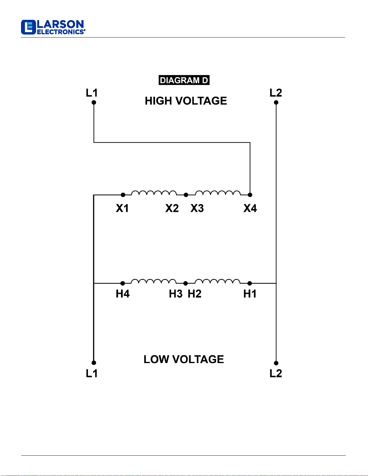
Wiring Diagram
WARNING: DO NOT SERVICE WHILE ENERGIZED! Tip: Use a voltmeter to check voltage!
Connection Guide:
1. Connect X2 and X3 together
2. Connect H2 and H3 together
3. Connect High Voltage L1 to X4
4. Connect Low Voltage L1 to H4 and X1
5. Connect High & Low Voltage L2 to H1

Larson Electronics, LLC Phone: (800) 369-6671 Fax: (903) 498-3364 www.larsonelectronics.com
7of 7
DIAGRAM D
BUCK & BOOST TRANSFORMERS
This manual suits for next models
1
Table of contents
Other LARSON Transformer manuals


