KSolare KSY-3000 User manual
User Manual
5G PRO INVERTER
KSY:- 3KW -12KW-3Ph
Three-Phase Grid-tied Solar Inverter

CATALOGUE
1. SYMBOLS ON THE LABEL ..................................................................................3
2. SAFETY AND WARNINGS ..................................................................................3
3. UNPACKING .........................................................................................................4
3.1 Scope of Delivery ..............................................................................................................5
3.2 Product Overview .............................................................................................................5
4. INSTALLING .........................................................................................................6
4.1 Installation Requirement ..................................................................................................6
4.2 Mounting Location...........................................................................................................7
4.3 Mounting ...........................................................................................................................8
4.4 Installing the PE cable ......................................................................................................8
5. COMMISSIONING .............................................................................................9
5.1 Safety Instructions ..........................................................................................................9
5.2 AC Wire Assembly and Connection ..............................................................................10
5.3 DC Wire Assembly and Connection ..............................................................................11
5.4 Residual Current Protection ...........................................................................................11
6. COMMUNICATION ...........................................................................................12
6.1 System monitoring via Datalogger - RS485/Wi-Fi /GPRS (Optional) ........................12
7. START UP AND OPERATION ...........................................................................14
7.1 Safety Check Before Start Up .........................................................................................14
7.2 Inverter LED Indicators ...................................................................................................15
8. DISCONNECTING FROM VOLTAGE RESOURCES .........................................16
10.
SYSTEM MAINTENANCE ..............................................................................19
9. Fault Finding ..............................................................................17
3
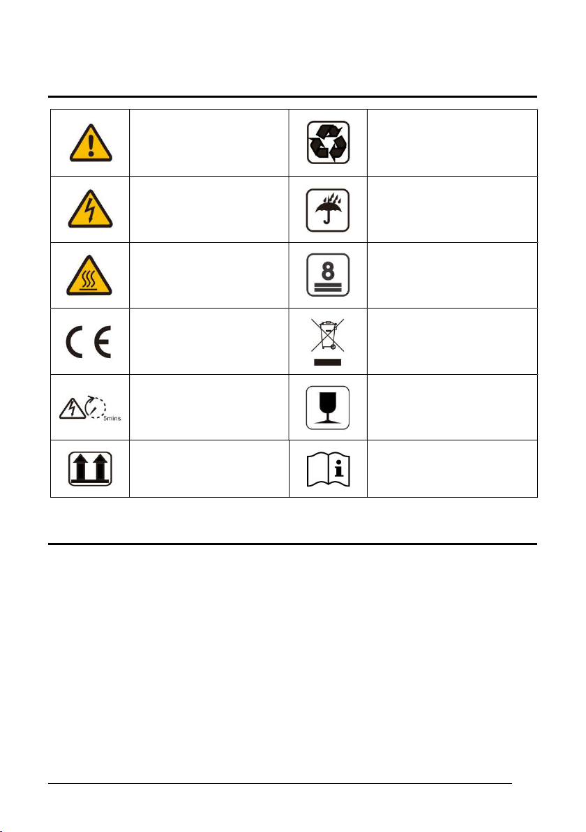
1. SYMBOLS ON THE LABEL
DANGER, WARNING AND
CAUTION
RECYCLABLE AND REUSABLE
HIGH VOLTAGE
AVOID CONTACT
AVOID DAMP AND MOISTURE
HIGH TEMPERATURE
AVOID CONTACT
SHIPMENT STACK LIMIT: 8
CE MARKS
DO NOT DISPOSE WITH
HOUSEHOLD WASTE
PROCEED OPERATIONS
AFTER 5 MINUTES
DISCHARGE
BREAKABLE ITEM
PLACE UPWARDS
USER MANUAL IN PACK
2. SAFETY AND WARNINGS
1. All persons who are responsible for mounting, installation, commissioning,
maintenance, tests, and service of KSOLARE inverter products must be suitably
trained and qualied for corresponding operations. They MUST beexperienced and
have knowledge of operation safety and professional methods. All installation
personnel must have knowledge of all applicable safety information, standards,
directives, and regulations.
2. The product must ONLY be connected and operated with PV arrays of protection
class II, in accordance with IEC 61730, application class A. The PV modules must also
4
be compatible with this product. Power resources other than compatible PV arrays
MUST not be connected and operate with the product.
3. When designing or constructing a PV system, all components MUST remain in their
permitted operating ranges, and their installation requirements MUST always be
fullled.
4. Under exposure to sunlight, the PV array may generate dangerous output in DC
voltage. Contacts with the DC wires, conductors and live components in the inverter
may result in lethal shocks.
5. High voltages ininverter could cause lethal electrical shocks. Before proceeding any
work, including maintenance and/or service, on the inverter, fully disconnect it from
all DC input, AC grid and other voltage sources. There MUST be a 5-minute waiting
time after the full disconnection.
6. The DC input voltage of the PV array MUST never exceed the maximum input
voltage of the inverter.
7. DO NOT touch parts of the inverter during operation as heat will beinduced and
these parts willexceed 60.
3. UNPACKING
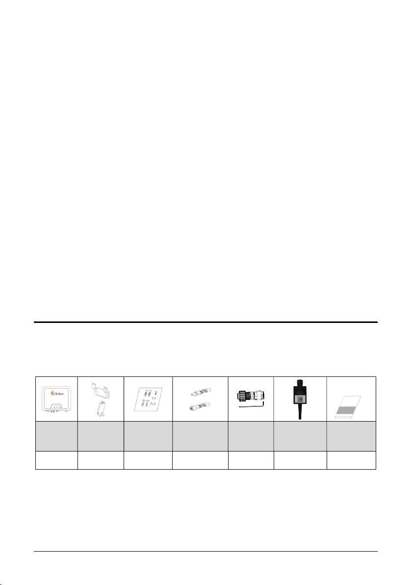
3.1 Scope of Delivery
Please inspect and check for completeness in the scope of delivery. Conrm with
purchase order.
INVERTER MOUNTING
BRACKET
MOUNTING
ACCESSORIES
DCPLUGS
(SEALED)
AC
CONNECTOR
COMMUNICATIO
NDATALOGGER
(OPTIONAL)
DOCUMENTS
1 1 1 2 1 1 1
5
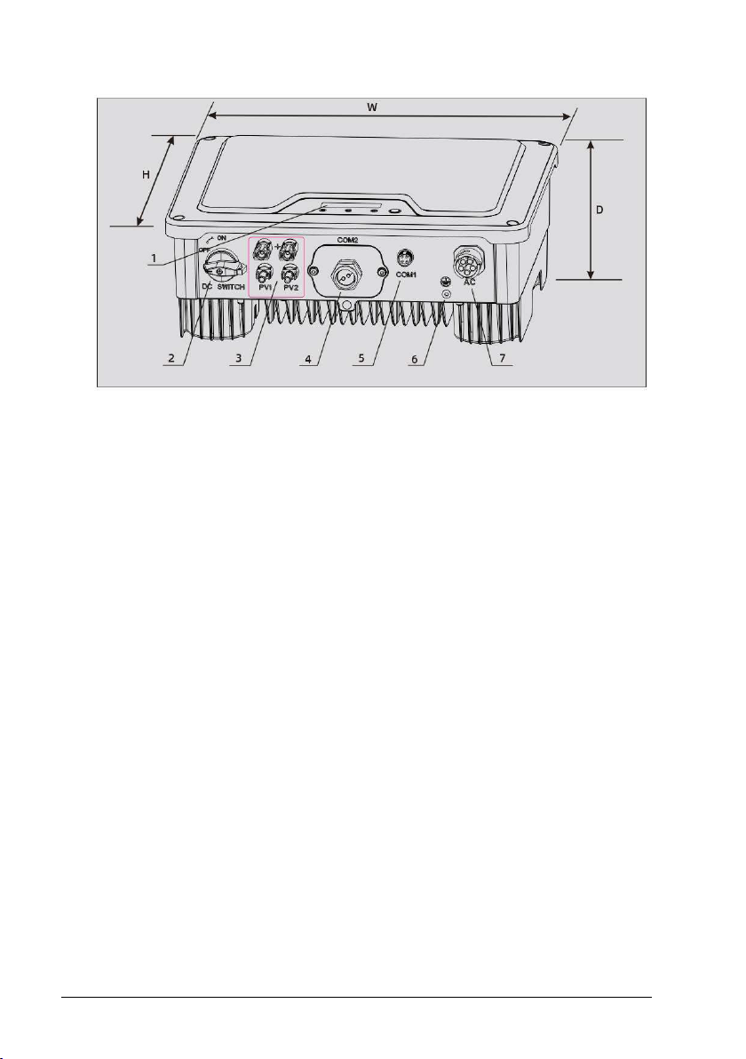
3.2 Product Overview
1LED&LCD or LED
2DC Switch
3PV Terminal (s)
4COM1: Wi-Fi/GPRS (Optional)
5COM2: RS485/METER/DRED
6Secondary PE Terminal
7AC Terminal
6
4. INSTALLING
4.1 Installation Requirement
1. Please install the inverter(s) in places that can avoid inadvertent contact.
2. Installation method, location and surface must be tting for the inverter’s weight and
dimensions.
3. Please install the inverter in an accessible location for operation, future maintenance
and service.
4. The inverter performance peaks at ambient temperature lower than 45.
5. When installing in residential or domestic environment, it is recommended to install
and mount the inverter on a solid, concrete wall surface. Mounting the inverter on
composite or plaster boards or walls with similar materials would induce noise during
its operation and is therefore not recommended.
6. DO NOT cover the inverter NOR place any objects on top of the inverter.
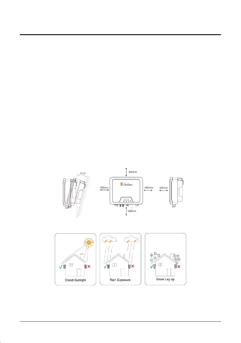
7. To ensure sucient room for heat dissipation and maintenance, the clearing space
betweeninverter(s) and other surroundings is indicated below for reference:
8. Avoid direct exposure to sunlight and rain and snow layup.
7
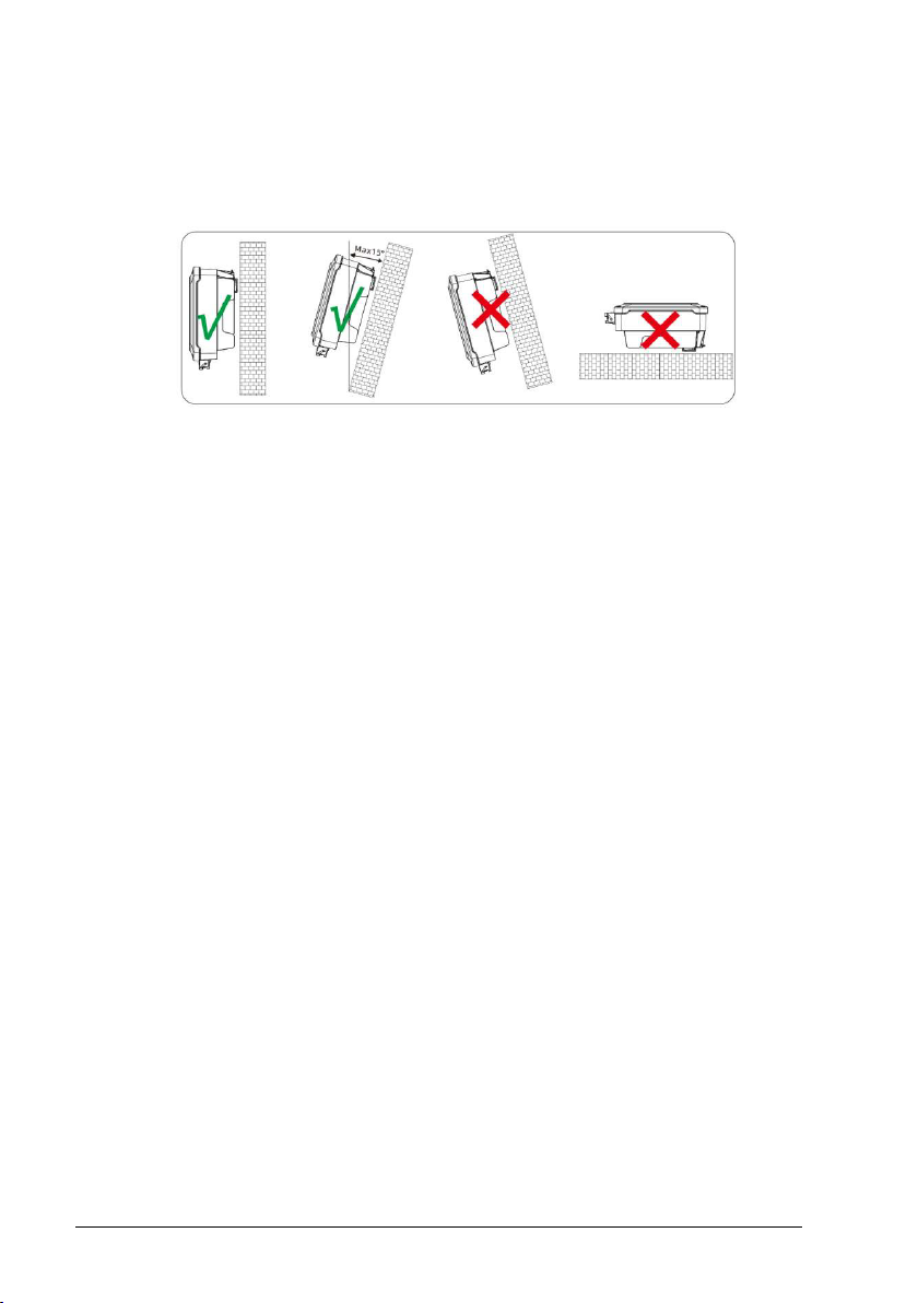
4.2 Mounting Location
1. DO NOT mount the inverter near any inammable materials.
2. DO NOT mount the inverter near any explosive materials.
3. DO NOT mount the inverter on tilting surface over 15° backwards. Please mount the
inverter on a vertical wall surface.
4. DO NOT mount the inverter on any surfaces tilting forward or to either sides.
5. DO NOT mount the inverter on a horizontal surface.
6. For easy installation and operation, please mount the inverter on a height that the
display could match eye level.
7. The bottom side where all commissioning terminals are equipped MUST always point
downwards.
8
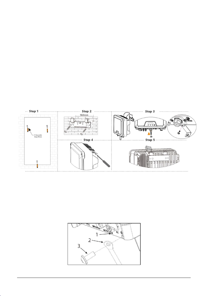
4.3 Mounting
1. Use the mounting paper guide as a template and drill holes of 10mm diameter and
70mm depth.
2. Fix the mounting bracket with the screws and expansion bolts packed in mounting
accessories.
3. Hold up the inverter and tilt it slightly forward. Hang up the inverter and attach it to
the mounting bracket. Check both sides of the heat sink to ensure its stably attached.
4. Use M5 screws (T25 screwdriver, torque 2.5 Nm) to attach the heat sink ns to the
mounting bracket.
5. It is recommended to attach the anti-theft lock to the inverter. Lock diameter φ4-
5.5mm recommended.
4.4 Installing the PE cable
1. Insert the grounding conductor into the suitable terminal lug and crimp the contact.
2. Align the terminal lug with the grounding conductor and the ground washer on the
screw. The teeth of the ground washer must be facing the housing.
3. Tighten it rmly into the housing (screwdriver type: T25, torque: 2.5Nm).

9
Information on grounding components:
Object Description
1 Housing
2 M5 terminal lug with protective conductor
3 M5×12 pan head screw
5. COMMISSIONING
5.1 Safety Instructions
1. Measure the frequency and voltage of grid connection and make sure they follow the
inverter’s grid connection specications.
2. An external circuit-breaker on the AC side (or a fuse) at 1.25*AC rated current is
strongly recommended.
3. Reliability of all earth connections must be tested and valid.
4. Before commissioning, disconnect the inverter and the circuit-breaker or fuse, and
prevent accidental reconnection.
10
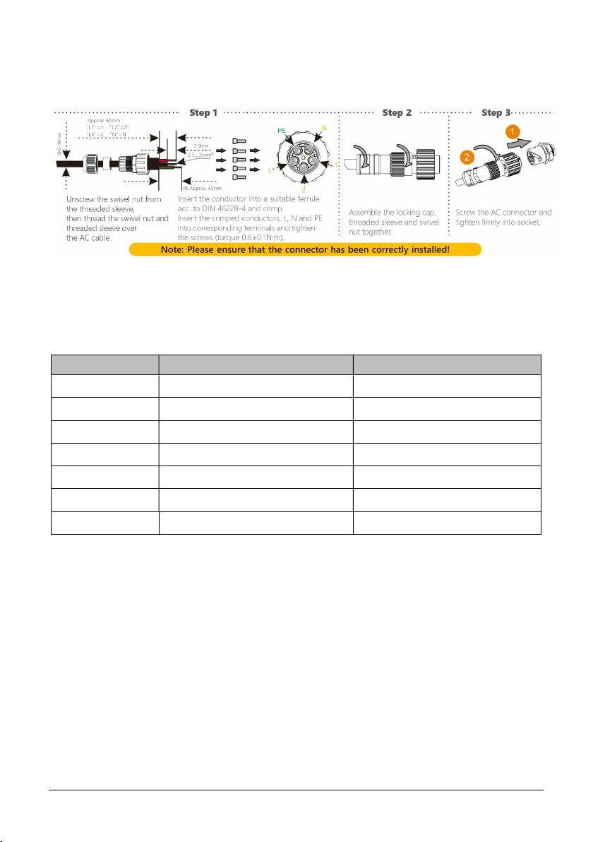
5.2 AC Wire Assembly and Connection
5.2.1 AC Commissioning
5.2.2 AC Switch Types
Please install an individual 2-stage miniature circuit breaker according to the following
specications.
Model Maximum output current(A)AC Breaker Rated current(A)
6150003-KSY
615.60004-KSY
615.80005-KSY
6190006-KSY
52310008-KSY
522.5100001-KSY
528100021-KSY
This manual suits for next models
6
Table of contents
Other KSolare Inverter manuals


