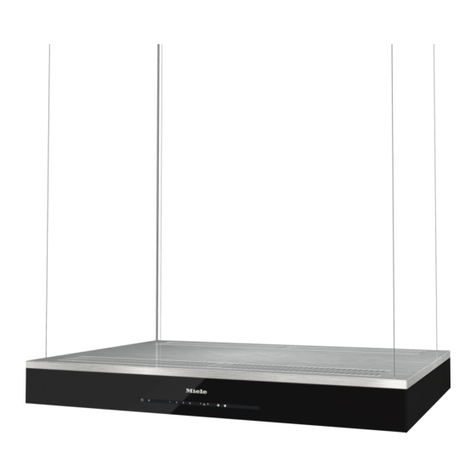
Kruger KCE 140PA User manual

VENTILATION FAN
WARNING
Models: KCE 140PA KCE 180PD
READ AND SAVE THESE INSTRUCTIONS
Installer: Leave this manual with the homeowner.
CAUTION
CLEANING & MAINTENANCE
OPERATION
TO REDUCE THE RISK OF FIRE, ELECTRIC SHOCK, OR INJURY TO PERSONS, OBSERVE THE
FOLLOWING:
1. Use this unit only in the manner intended by the manufacturer. If you have questions, contact the
manufacturer at the address or telephone number listed in the warranty.
2. Before servicing or cleaning unit, switch power off at service panel and lock the service discon-
necting means to prevent power from being switched on accidentally. When the service discon-
necting means cannot be locked, securely fasten a prominent warning device, such as a tag, to the
service panel.
3. Installation work and electrical wiring must be done by a qualified person(s) in accordance with all
applicable codes and standards, including fire-rated construction codes and standards.
4. Sufficient air is needed for proper combustion and exhausting of gases through the flue (chimney)
of fuel burning equipment to prevent backdrafting. Follow the heating equipment manufacturer’s
guideline and safety standards such as those published by the National Fire Protection Association
(NFPA), and the American Society for Heating, Refrigeration and Air Conditioning Engineers
(ASHRAE), and the local code authorities.
5. When cutting or drilling into wall or ceiling, do not damage electrical wiring and other hidden utili-
ties.
6. Ducted fans must always be vented to the outdoors.
7. Acceptable for use over a tub or shower when connected to a GFCI (Ground Fault Circuit Interrupt-
er) - protected branch circuit (ceiling installation only).
8. This unit must be grounded.
1. For general ventilating use only. Do not use to exhaust hazardous or explosive materials and vapors.
2. This product is designed for installation in ceilings up to a 12/12 pitch (45 degree angle). Duct connector must point up.
DO NOT MOUNT THIS PRODUCT IN A WALL.
3. To avoid motor bearing damage and noisy and/or unbalanced impellers, keep drywall spray, construction dust, etc. off
power unit.
4. Please read specification label on product for further information and requirements.
For quiet and efficient operation, long life, and attractive appearance - lower or remove grille and vacuum interior of unit
with the dusting brush attachment.
The motor is permanently lubricated and never needs oiling. If the motor bearings are making excessive or unusual
noises, replace the motor with the exact service motor. The impeller should also be replaced.
See “CONNECT ELECTRICAL WIRING” for details.
IGB056B.E0/2106

PLAN THE INSTALLATION
TYPES OF TYPICAL INSTALLATIONS
1. Do not use in a cooking area.
2. Two ways to connect ductwork to a factory-shipped unit.
ASSEMBLY INSTRUCTIONS
1. Housing mounted to I-joists (Start at “ASSEMBLY INSTRUCTIONS 1”)
2. Housing mounted to joists (Start at “ASSEMBLY INSTRUCTIONS 1” )
3. Housing mounted to truss (Start at step “ASSEMBLY INSTRUCTIONS 2”)
1. MOUNT HOUSING TO JOIST OR I-JOIST.
ROOF CAP*
(with built-in
damper)
ROUND
DUCT* WALL CAP*
(with built-in
damper)
*Purchase
separately
POWER
CABLE*
INSULATION*
(Place around and
over Fan Housing.)
Seal gaps
around
Housing.
FAN
HOUSING
ROUND
ELBOW(S) *
Seal duct
joints with
tape.
Keep duct
runs short
2. Mount with mountion holes and hanger bar
a. Hold the housing so that it is in contact with the bottom of the joist.
b. Attach the housing with four (4) screws to the joist through the
holes in each mounting flange.
a. Slide one hanger bar into the channel on the housing and adjust as
needed to fit between framing.
b. Hold housing in place so that the housing contact the bottom of the
joist, Screw housing to joist through the hole of the housing .
c. Screw the hanger bar onto the other side of joist through the hole.
d. Screw hanger bar to housing with screw.
e. Refer to the right diagram.
3. Mount to I-joist
a. Slide one hanger bar into channel on the housing and adjust as
needed.
b. Hold housing in place so that the housing contacts the bottom of
the joist.
c. Screw housing to joist through the hole of the housing.
d. Screw the hanger bar onto the joist through the hole.
e. Screw hanger bar to housing with screw .
2

ASSEMBLY INSTRUCTIONS
5. INSTALL ROUND DUCTWORK
a. Connect the round ductwork (not included) to the damper/duct
connector, and run the ductwork to a roof or wall cap (not included).
b. Using tape (not included), secure all the ductwork connections so that
they are air tight.
c. Insulated flexible duct is recommended for the quietest possible
installation. If rigid duct is used, a short (1-3 feet) section of insulated
flexible duct will ensure quiet operation.
The ducting from this fan to the outside of building has a strong effect
on the air flow, noise and energy use of the fan. Use the shortest,
straightest duct routing possible for best performance, and avoid
installing the fan with smaller ducts than recommended. Insulation
around the ducts can reduce energy loss and inhibit mold growth.
Fans installed with existing ducts may not achieve their rated air flow.
4. Install DUCT AND BLOWER ASSEMBLY
Hole Hole
Hole
a.Install duct from the inside of the housing;Fix the duct by the tab.
b.Fix the BLOWER ASSEMBLY to the housing by 3 screws.
RETROFIT INSTALLATION
1. Remove wire panel and blower assembly before installation.
2. Fold mounting ears flat against housing. Blower
assembly
Wire
panel
3. Enlarge ceiling opening to 9-1/2” by 9-1/2”, leave ductwork
and wiring in place.
4. Connect wiring according to the wiring diagram.Re-install wire
panel.
5. Mounting fan
a. Mount with additional mounting holes
The interior of the fan housing contains additional mounting
holes in case exterior mounting is not possible.
Screw or nail the fan housing directly to the framing or joists.
Remove the blower assembly as directed in the service parts
section of this manual to gain access to the additional mount-
ing holes.
b. Mount with hole of the flange
Use screws (included) to screw fans to the ceiling through the
holes of the housing.
6. Connect duct
Pull existing ducting through housing discharge opening and
tape ducting to duct connector. Push connector/ducting back
through opening,fix the duct by the tab.
7. Install the blower assembly.
additional mounting holes
Hole
Hole
Hole
Tab
9-1/2”
9-1/2”
3

WARRANTY
INSTALL GRILLE
SERVICE PARTS
A
Run 220V AC house wiring to the location of the fan. Use only UL-approved connectors (not included) to attach the house
wiring to the wiring plate. Refer to the wiring diagram, and connect the wires as shown.
CONNECT ELECTRICAL WIRING
Install ceiling material to complete the ceiling construction and cut around the fan
housing.
To attach the grille assembly to the fan housing, pinch the grille springs on the
sides of the grille assembly and position the grille into the housing with the grille
springs in the appropriate slots. Push the grille assembly towards the ceiling to
secure.
UNIT
BLACK (BLK)
SWITCH BOX
FAN
POWER SUPPLY
220V AC
GROUND (GRD)
WHITE (WHT)
WIRING
PLATE
FAN
RECEPTACLE
FAN
UNIT
SWITCH BOX
LINE
IN
ON/OFF
SWITCH
BLK
BLK
WHT
WHT
GRDGRD
1
2
3
4
5
6
c
a
b
8
7
9
11
12
10
d
d
Grille Assembly (includes part 2)
* Blower Assembly includes part 3, 4, 5, 6, 7, a, b
Replacement installation: Remove the screw (part a), then take out the blower
assembly from the housing (part 8). Replace the broken parts.
WARNING: Ensure that the fan is switched off from the supply mains before replacing.
PART PART NAME Qty.
1
2
3
4
5
6
7
8
9
10
Housing
Blower Wheel
Blower
Wire Panel / Harness Assembly
Motor
1
2
1
1
1
1
1
1
1
Wiring Plate
4
11
Damper/Duct Connector
1
12
Power Box (For KCE 140PD)
1
Motor Plate
Grille Spring
Hanger Bars
a3Screw
b3Screw
c4Screw
d2Screw
This warranty covers all defects in workmanship or materials for:
The mechanical and electrical parts contained in this product, for a period of 12 months, from the date of purchase. You must keep and be able to
provide your original sales receipt as proof of the date of purchase. This warranty is covered the original retail purchaser of this product. The manufac-
turer will repair or replace, in your home, any mechanical or electrical part which proves defective in normal household use for a period of 12 months.
THIS WARRANTY DOES NOT COVER:
• Damages from improper installation
• Damages from shipping
• Damages from misuse, abuse, accident, alteration, lack of proper care and maintenance
• Damages from service by persons other than an authorized dealer or service center.
• Labor, service, transportation and shipping charges for the removal of defective parts and for installation of a replacement part, beyond the initial
12-month period.
This warranty does not extend to fluorescent lamp starters and tubes.
THIS LIMITED WARRANTY IS GIVEN IN LIEU OF ALL OTHER WARRANTIES, EXPRESSED OR IMPLIED, INCLUDING THE WARRANTIES OF
MERCHANTABILITY AND FITNESS FOR A PARTICULAR PURPOSE.
The remedy provided in this warranty is exclusive and is granted in lieu of all other remedies. This warranty does not cover incidental or consequential
damages. Some states do not allow the exclusion of incidental or consequential damages, so this limitation may not apply to you. Some states do not
allow limitations on how long an implied warranty lasts, so this limitation may not apply to you. This warranty gives you specific legal rights, and you may
also have other rights, which vary from state to state.
4
This manual suits for next models
1
Table of contents
Other Kruger Ventilation Hood manuals

Kruger
Kruger KA300 User manual

Kruger
Kruger KM300 User manual

Kruger
Kruger KCE 100PA User manual

Kruger
Kruger KH 300 User manual

Kruger
Kruger KR-300 Alto-R User manual

Kruger
Kruger ALTO-T User manual

Kruger
Kruger Alto S User manual

Kruger
Kruger Ecowatt Drive K354 Series Installation guide

Kruger
Kruger KA300 User manual

Kruger
Kruger Ecowatt K320 Series Installation guide