KRAL EET 32 User manual

Operating instructions
KRAL Temperature Sensors
EET 32/EET 33/EET 34/EET 38
OII 08en-GB
Edition 2021-07
Original instructions
www.kral.at

Table of contents
1 About this document ..................................................... 3
1.1 General information .......................................................3
1.2 Target groups ................................................................3
1.3 Associated documents ..................................................3
1.4 Symbols.........................................................................3
1.4.1 Danger levels ....................................................3
1.4.2 Danger signs.....................................................3
1.4.3 Symbols in this document .................................4
2 Safety .............................................................................. 4
2.1 Correct use ....................................................................4
2.2 Foreseeable misuse ......................................................4
2.3 Fundamental safety instructions....................................4
3 Technical data ................................................................ 5
3.1 Operating limits..............................................................5
3.2 Selecting the temperature sensor..................................5
3.3 EET 32/EET 33/EET 34 data sheet...............................6
3.4 EET 38 data sheet.........................................................7
4 Function description...................................................... 8
4.1 Structure ........................................................................8
4.2 Functional principle........................................................8
5 Transportation, storage................................................. 8
5.1 Unpacking and checking the state of delivery ...............8
5.2 Storing the sensor .........................................................8
6 Installation, removal and connection........................... 9
6.1 Dangers during installation, removal and connection....9
6.2 Installing the EET in OME .............................................9
6.3 Installing the EET in OMG ...........................................10
6.4 Installing the EET in OMP ...........................................10
6.5 Installing the EET in the piping ....................................11
6.6 Connecting the extension cable ..................................12
6.7 Expanding the EET......................................................12
7 Disposal ........................................................................ 12
7.1 Temperature sensor disposal ......................................12
8 Troubleshooting........................................................... 13
8.1 Possible faults .............................................................13
8.2 Troubleshooting...........................................................13
9 Accessories .................................................................. 13
9.1 Junction box ................................................................13
2OII 08en-GB Edition 2021-07 Operating instructions

1 About this document
1.1 General information
1 About this document
1.1 General information
These instructions form part of the product and must be kept for future reference. Furthermore please
observe the associated documents.
1.2 Target groups
The instructions are intended for the following persons:
oPersons who work with the product
oOperator-owners who are responsible for the use of the product
Persons who work with the product must be qualified. The qualification ensures that possible dangers
and damage to property that are connected to the activity are detected and avoided. These persons
are qualified personnel who carry out the work properly due to their training, knowledge and experience
and on the basis of the relevant provisions.
Information on the qualification of the personnel is provided separately at the beginning of the indi-
vidual chapters in these instructions. The following table provides an overview.
Target group Activity Qualification
Fitter Mounting, connection Qualified personnel for mounting
Electrician Electrical connection Qualified personnel for electric installation
Trained personnel Delegated task Personnel trained by the operator-owner who
know the task delegated to them and the possible
dangers arising through improper behaviour.
Tab.1: Target groups
1.3 Associated documents
oDeclaration of conformity according to EU Directives 2011/65/EU and 2014/30/EU
oCorresponding flowmeter operating instructions
oCorresponding electronics operating instructions
1.4 Symbols
1.4.1 Danger levels
Signal word Danger level Consequences of non-observance
DANGER Immediate threat of danger Serious personal injury, death
WARNING Possible threat of danger Serious personal injury, invalidity
CAUTION Potentially dangerous situation Slight personal injury
ATTENTION Potentially dangerous situation Material damage
1.4.2 Danger signs
Meaning Source and possible consequences of non-observance
Electrical voltage Electrical voltage causes serious physical injury or death.
Operating instructions OII 08en-GB Edition 2021-07 3

2 Safety
2.1 Correct use
1.4.3 Symbols in this document
Meaning
Warning personal injury
Safety instruction
Request for action
1.
2.
3.
Multi-step instructions for actions
Action result
Cross-reference
2 Safety
2.1 Correct use
oTemperature sensors are designed for use with a KRAL flowmeter or for installation in the piping
system.
oUse the temperature sensor only within the operating limits specified in the “Technical data” sec-
tion. Deviating operating data can result in damage. If in doubt, contact the manufacturer.
2.2 Foreseeable misuse
oAny use that extends beyond the proper use or any other use is misuse.
2.3 Fundamental safety instructions
The following safety instructions must be observed strictly:
oRead and observe these operating instructions carefully.
oObserve the operating instructions for the flowmeter and the electronics.
oHave work only carried out by qualified/trained personnel.
oWear personal protective equipment and work carefully.
oDepending on the operating conditions, the service life of the sensors is limited by vibrations, tem-
perature influences or ageing. Regularly replace any parts that jeopardise safe operation.
oShield the connecting lines of the sensor connections and lay them separately from the supply
and measuring lines.
oEnsure that the power supply is correct.
oAlways equip systems with greater danger potential with alarm equipment.
oMaintain and check protective/alarm equipment regularly.
4OII 08en-GB Edition 2021-07 Operating instructions

3 Technical data
3.1 Operating limits
3 Technical data
3.1 Operating limits
The following table shows the operating limits of the temperature sensors that must not be exceeded.
Parameter Unit Type
EET32 EET33 EET34 EET38
Max. operating pressure [bar] 300 100
Medium temperature min. - max. [°C] -50...260
Tab.2: Operating limits
In addition, the operating limits of the corresponding flowmeter and the additional sensors must be ob-
served.
3.2 Selecting the temperature sensor
Flowmeter Installation in pipeline
Size Series
OME OMG OMP
13 EET32 EET34/EET38 – Any temperature sensor
possible
20 EET32 EET33 EET33
32 EET32 EET34/EET38 EET34/EET38
52 EET33 EET34/EET38 EET33
68 – EET34/EET38 –
100 – EET34/EET38 –
140 – – –
Operating instructions OII 08en-GB Edition 2021-07 5

3 Technical data
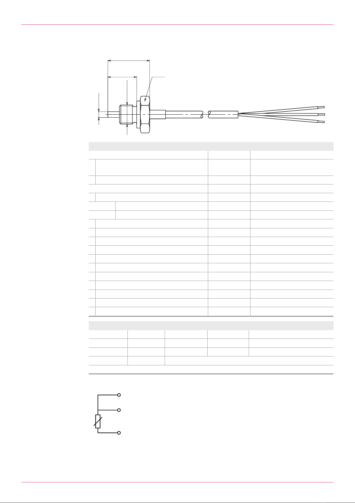
3.3 EET 32/EET 33/EET 34 data sheet
L1
L2
B
G1/4"
D
Specification Unit Data
Electrical specification
oSensor type Pt100, EN IEC 60751
Class B, 3-wire
oLinearity ±0.1 % of final value
Mechanical specification
oRange of application
oMedium temperature [°C] -50 ... +260
oAmbient temperature [°C] -40 ... +150
oPressure [bar] 300
oHousing material 1.4571
oSeal FPM
oConnection type Cable with wire ends
oCable sheath Teflon (PTFE)
oWire cross-section [mm2] 3x0.34
oCable diameter [mm] 3.3
oCable length [m] 3
oWeight [g] 110
oDegree of protection IP65
oTightening torque [Nm] 30
Dimensions Unit EET32 EET33 EET34
oD[mm] 4 6 6
oL1 [mm] 20 25 35
oL2 [mm] 29 34 44
oBSW 22
The temperature sensor type/version is indicated on the hexagon.
Tab.3: Temperature sensor dimensions and marking
2
1
3
Fig.1: Connection diagram
1Red
2Red
3White
6OII 08en-GB Edition 2021-07 Operating instructions

3 Technical data
3.4 EET 38 data sheet
L1
L2
B
G1/4"
D
Specification Unit Data
Electrical specification
oSensor type Pt100, EN IEC 60751
Class B, 3-wire
oLinearity ±0.1 % of final value
Mechanical specification
oRange of application
oMedium temperature [°C] -50 ... +260
oAmbient temperature [°C] -40 ... +150
oPressure [bar] 100
oHousing material 1.4571
oSeal FPM
oConnection type Cable with wire ends
oCable sheath Teflon (PTFE)
oWire cross-section [mm2] 3x0.34
oCable diameter [mm] 3.3
oCable length [m] 3
oWeight [g] 110
oDegree of protection IP65
oTightening torque [Nm] 30
General information
Use in potentially explosive atmospheres According to 2014/34/EU (ATEX)
oEx marking ll 2G Ex ia IlC T1...T6 Gb
Dimensions Unit EET38
oD[mm] 6
oL1 [mm] 35
oL2 [mm] 44
oBSW 22
The temperature sensor type/version is indicated on the hexagon.
Tab.4: Temperature sensor dimensions and marking
2
1
3
Fig.2: Connection diagram
1Red
2Red
3White
Operating instructions OII 08en-GB Edition 2021-07 7

4 Function description
4.1 Structure
4 Function description
4.1 Structure
1
2
3
4
Fig.3: Temperature sensor structure
1Thread
2Seal
3Hexagon
4Sensor cable
4.2 Functional principle
Temperature sensors of the EET series are equipped with Pt100 elements. The measurements are
based on the change in resistance of platinum under the influence of temperature. Due to the three-
wire circuit of the sensor, long connection cables can also be used without falsifying the measurement
result.
The temperature sensor is screwed into the hole provided in the flow meter or into the piping.
5 Transportation, storage
5.1 Unpacking and checking the state of delivery
Personnel qualification: oTrained personnel
1. Upon delivery check the product for damage during transportation.
2. Report damage during transportation immediately to the manufacturer.
3. Dispose of packing material in accordance with the locally applicable regulations.
5.2 Storing the sensor
Store the sensor in its original packaging in a cool and dry location.
8OII 08en-GB Edition 2021-07 Operating instructions

6 Installation, removal and connection
6.1 Dangers during installation, removal and connection
6 Installation, removal and connection
6.1 Dangers during installation, removal and connection
The following safety instructions must be observed strictly:
oAll work must only be carried out by electricians.
oDo not operate the sensor in the vicinity of strong high-frequency electromagnetic fields. These
can lead to incorrect measurement or destruction of the sensor.
oShield the connecting lines of the sensor connections and lay them separately from the supply
and measuring lines.
oEnsure that the power supply is correct.
oSwitch off and depressurise the system before installing or removing the sensor.
oMake sure that the cable is loosely twisted when installing or removing the sensor.
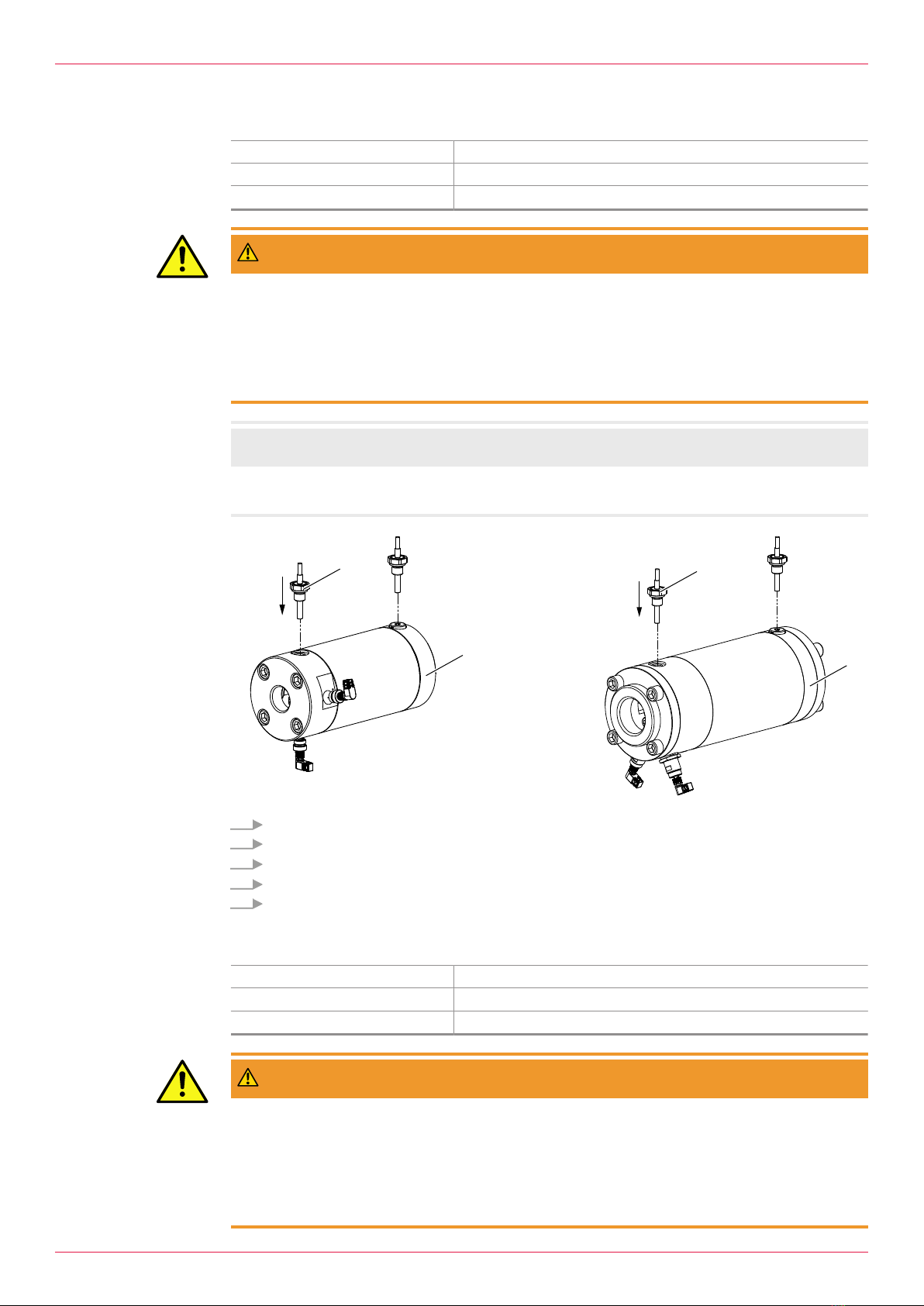
6.2 Installing the EET in OME
Personnel qualification: oElectrician
Personal protective equipment: oWork clothing
Aids: oTorque wrench
WARNING
Risk of injury through escaping medium.
Media can be hot, poisonous, combustible and caustic.
► Before installing the sensor, switch off the system and depressurise it.
► Wear personal protective equipment at all times during operation. Pay attention to face protection.
► Collect any escaping medium safely and dispose of it in an environmentally compatible manner in
accordance with the applicable local regulations.
ATTENTION
Incorrect installation destroys the sensor
► Select a suitable temperature sensor and insert the support disc with O-ring into the sensor bore.
1
2
3
4
OME 13 – 32 OME 52
1
4
1. Remove the screw plug, support washer2 and O-ring3.
2. Clean the sensor bore. No foreign bodies should penetrate the flowmeter4 or piping system.
3. Place support disc2 with inserted O-ring3 in the sensor bore.
4. Select suitable sensor1, Ä Technical data,Page5.
5. Screw the sensor into the sensor bore as far as it will go, maximum tightening torque 30 Nm.
6. Connect the sensor cable, observing the connection diagram. Ä Technical data,Page5.
Operating instructions OII 08en-GB Edition 2021-07 9

6 Installation, removal and connection
6.3 Installing the EET in OMG
Personnel qualification: oElectrician
Personal protective equipment: oWork clothing
Aids: oTorque wrench
WARNING
Risk of injury through escaping medium.
Media can be hot, poisonous, combustible and caustic.
► Before installing the sensor, switch off the system and depressurise it.
► Wear personal protective equipment at all times during operation. Pay attention to face protection.
► Collect any escaping medium safely and dispose of it in an environmentally compatible manner in
accordance with the applicable local regulations.
ATTENTION
Incorrect installation destroys the sensor
► Select the correct installation location.
X
X
11
22
OMG 32 OMG 52
1. Select the correct bore and remove the screw plug from the sensor bore.
2. Clean the sensor bore. No foreign bodies should penetrate the flowmeter2 or piping system.
3. Select suitable sensor1, Ä Technical data,Page5.
4. Screw the sensor into the sensor bore as far as it will go, maximum tightening torque 30 Nm.
5. Connect the sensor cable, observing the connection diagram. Ä Technical data,Page5.
6.4 Installing the EET in OMP
Personnel qualification: oElectrician
Personal protective equipment: oWork clothing
Aids: oTorque wrench
WARNING
Risk of injury through escaping medium.
Media can be hot, poisonous, combustible and caustic.
► Before installing the sensor, switch off the system and depressurise it.
► Wear personal protective equipment at all times during operation. Pay attention to face protection.
► Collect any escaping medium safely and dispose of it in an environmentally compatible manner in
accordance with the applicable local regulations.
10 OII 08en-GB Edition 2021-07 Operating instructions

This manual suits for next models
3
Table of contents
Popular Temperature Controllers manuals by other brands

SMC Networks
SMC Networks Thermo-con INR-244-639 Operation manual

eltherm
eltherm Ex-TC It Series operating instructions

Omron
Omron C200H-TV Series Operation manual

industrie technik
industrie technik CA1 instructions

dixell
dixell XR420C Installing and operating instructions

Opt Lasers
Opt Lasers TEC-8A-24V-PID-HC operating manual