KNF NF 1.30 User manual

KNF Flodos AG BA_NF1.30_EN_04_067674.docx
Translation of original Operating and Installation Instructions Keep for future reference!
DIAPHRAGM LIQUID PUMP
NF 1.30
Operating and
Installation
Instructions
Read and observe these Oper-
ating and Installation Instruc-
tions.
An additional letter prefixing
the
NF model code is a country-
specific designation, with no
technical relevance.
Contents Page
1. About this document ................................................................. 2
2. Use ........................................................................................... 3
3. Safety ....................................................................................... 4
4. Technical data .......................................................................... 6
5. Assembly and function ............................................................. 8
6. Installation and connection ....................................................... 9
7. Operation ................................................................................ 11
8. Servicing ................................................................................. 14
9. Troubleshooting ...................................................................... 17
10. Spare Parts and Accessories ................................................. 19
11. Return of the pump ................................................................. 20
KNF Flodos AG
Wassermatte 2
6210 Sursee, Switzerland
Tel +41 (0)41 925 00 25
Fax +41 (0)41 925 00 35
www.knf.com
info.flodos@knf.com
NF 1.30 KT DCG 12V
DCG
1.30
NF
Supply voltage [Ch. 4]
-
/ PMLxxxx / PLxxxx [Ch. 1]
KT / TT [Ch. 4]

About this document Diaphragm Liquid Pump NF 1.30
KNF Flodos AG BA_NF1.30_EN_04_067674.docx
2 Translation of original Operating and Installation Instructions
1. About this document
1.1. Use of the Operating and Installation Instruc-
tions
The Operating and Installation Instructions are part of the pump.
Forward the Operating and Installation Instructions to any
subsequent owners of the pump.
Customer-specific project pumps (pump models which begin with
"PL" or "PML") may differ from the Operating and Installation
Instructions.
In the case of project pumps, take note of any additionally
agreed specifications.
1.2. Symbols and markings
Warning
WARNING
This symbol indicates a potential danger.
It also indicates the possible consequences of failure
to observe the warning. The signal word (e.g. "Warn-
ing") indicates the level of danger.
Here you will see
actions for avoiding the danger
and potential consequences.
Danger levels
Signal word
Meaning Consequences if not observed
DANGER warns of immedi-
ate danger
Consequences are death or
serious injury and/or serious
property damage.
WARNING
warns of potential
danger
Death or serious injury and/or
serious damage to property are
possible.
CAUTION warns of a poten-
tially dangerous
situation
Minor injury or damage to prop-
erty are possible.
Tab. 1
Other information and symbols
This indicates a required activity (step) that must be carried
out.
This indicates the first step of an activity to be carried out. Any
additional steps are numbered consecutively.
This symbol indicates important information.
Project pumps

Diaphragm Liquid Pump NF 1.30 For your notes
KNF Flodos AG BA_NF1.30_EN_04_067674.docx
Translation of original Operating and Installation Instructions 3
2. Use
2.1. Intended use
The pumps are intended for transferring and metering liquids.
Owner's responsibility
Install and operate the pumps only under the operating parameters
and conditions described in Chapter 4. Technical data.
Only completely installed pumps may be taken into service.
Before transferring or metering a medium, check whether the
medium can be transferred danger-free in the specific application
case.
Before using a medium, check the compatibility of the materials of
the pump head, pump housing, diaphragm and valves with the
medium.
The temperature of the medium must lie within the permissible
temperature range (see Chapter 4).
The transferred medium should not contain particles as these can
prevent the pump from working correctly. If this cannot be guaran-
teed, a filter < 100 m with sufficiently large filter area must be
used upstream of the pump.
Filters may be ordered as accessories, see Spare Parts and
Accessories (Chapter 10).
2.2. Improper use
DANGER
The pumps must not be operated in an explosive
atmosphere.
Please contact your local KNF partner for special designs that
are not included in the technical specification (www.knf.com).
Operating parameters and
conditions
Requirements for media
to be transferred
Risk of explosion

Safety Diaphragm Liquid Pump NF 1.30
KNF Flodos AG BA_NF1.30_EN_04_067674.docx
4 Translation of original Operating and Installation Instructions
3. Safety
Observe the safety precautions in Chapters
6. Installation and connection and 7. Operation.
The pumps are built according to the generally recognised rules of
technology and in accordance with the pertinent occupational
safety and accident prevention regulations. Nevertheless, potential
dangers during use can result in injuries to the user or others, or in
damage to the pump or other property.
Only use the pumps when they are in a good technical and proper
working order, in accordance with their intended use, observing the
safety advice within the Operating and Installation Instructions, at
all times.
Make sure that only trained and instructed personnel or specially
trained personnel work on the pumps. This especially applies to
assembly, connection and servicing work.
Make sure that the personnel has read and understood the Operat-
ing and Installation Instructions, and in particular the "Safety"
chapter.
Always ensure adherence to all pertinent accident prevention and
safety regulations when working on and operating the pump.
When transferring dangerous media, observe the safety regula-
tions for handling such media.
Always ensure adherence to all information stickers on the pumps,
such as flow direction arrows and type plates, and keep stickers in
a legible condition.
All replacement parts should be properly stored and disposed of in
accordance with the applicable environmental protection regula-
tions. Ensure adherence to the pertinent national and international
regulations. This applies especially to parts contaminated with toxic
substances.
Dispose of all packaging in an environmentally-appropriate
manner. The packaging materials are recyclable.
Dispose of end-of-life equipment in an environmentally
friendly manner. Use appropriate waste collection systems
for the disposal of end-of-life equipment. Used pumps
contain valuable recyclable materials.
Personnel
Working in a
safety-conscious manner
Handling dangerous media
Notes
Environmental protection
Disposal

Diaphragm Liquid Pump NF 1.30 For your notes
KNF Flodos AG BA_NF1.30_EN_04_067674.docx
Translation of original Operating and Installation Instructions 5
The pumps comply with the fundamental requirements of Directive
2011/65/EU (RoHS2).
For the purposes of the Machinery Directive 2006/42/EC, pumps
are “partly completed machinery", and are therefore to be regarded
as not ready for use. Partly completed machinery may not be
commissioned until such time as it has been determined that the
machine in which the partly completed machinery is to be assem-
bled conforms to the provisions of the Machinery Directive
2006/42/EC. The essential requirements of Annex I of Directive
2006/42/EC (general principles) are applied and observed.
The following harmonized standards are met:
NF 1.30 DCG
EN 55014 - 1: 2001
All repairs to the pumps must be carried out by the responsible
KNF customer service team.
Use only genuine parts from KNF for servicing work.
EU directives/standards
Customer service and
repairs

Technical data Diaphragm Liquid Pump NF 1.30
KNF Flodos AG BA_NF1.30_EN_04_067674.docx
6 Translation of original Operating and Installation Instructions
4. Technical data
Pump materials
The pump type KT stands for:
Assembly Material1)
Pump head* PP
Valve socket PP / FFKM
Sealing washer FFKM
Diaphragm PTFE
Tab. 2 1) according to DIN ISO 1629 and 1043.1
* The pump head comprises an intermediate plate and a connect-
ing plate (Fig. 1).
The pump type TT stands for:
Assembly Material1)
Pump head* PVDF
Valve socket PVDF / FFKM
Sealing washer FFKM
Diaphragm PTFE
Tab. 3 1) according to DIN ISO 1629 and 1043.1
Diaphragm Liquid Pump NF 1.30 For your notes
KNF Flodos AG BA_NF1.30_EN_04_067674.docx
Translation of original Operating and Installation Instructions 7
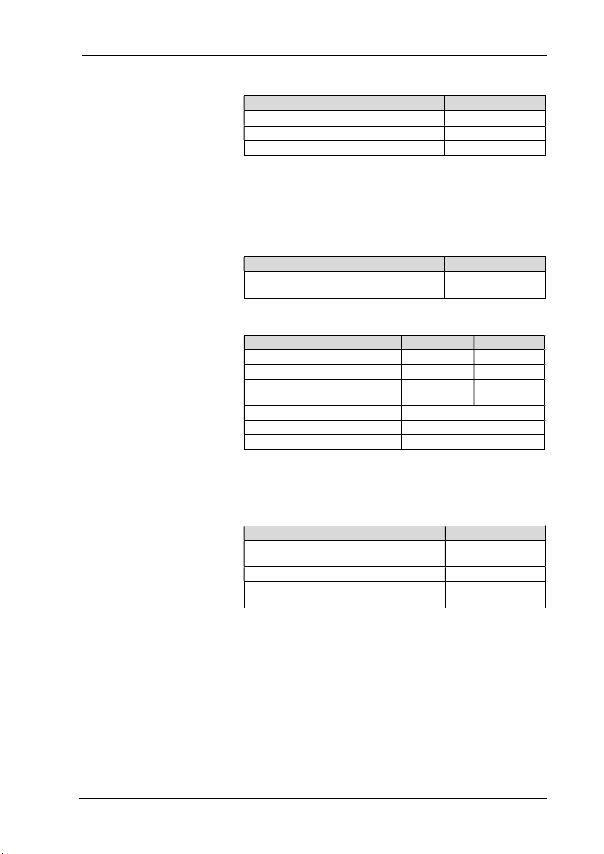
Hydraulic ratings
Parameter Value
Flow rate [ml/min] 1), 2) 170
Permissible pressure [bar g] 4
Suction head [mWG] 5
Tab. 4
1) Measured with water at 20°C / at atmospheric pressure
2) Flow rates may vary from the values shown, depending on fluid
viscosity, pump head material and the hoses / hose connectors
used.
Hydraulic connections
Parameter Value
Recommended hose size ID [mm] / OD
[mm]
4/6
Tab. 5
Specifications NF 1.30 DCG
Motor voltage 12V 24V
Power consumption [W] 10.1 11
Max. I load [A] 0.61 0.35
Max. permissible operating
current [A] 0.84 0.46
Lead size [-] AWG28
Protection class [-] IP00
Weight1) [g] 220
Tab. 6
1) The weight may differ slightly from the stated value, depending on
the version.
Other parameters
Parameter Value
Permissible
ambient temperature range (°C)
+5 to +40
Permissible media temperature range (°C) +5 to +80
Permissible kinematic viscosity of medium
[cSt]
≤150
Tab. 7

Assembly and function Diaphragm Liquid Pump NF 1.30
KNF Flodos AG BA_NF1.30_EN_04_067674.docx
8 Translation of original Operating and Installation Instructions
5. Assembly and function
Assembly
1 Outlet
2 Inlet
3 Head plate
4 Connecting plate
5 Intermediate plate
6 Motor
Fig. 1: Diaphragm liquid pump
1 Outlet valve
2 Inlet valve
3 Working chamber
4 Diaphragm
5 Eccentric
6 Connecting rod
7 Pump drive
Fig. 2: Pump assembly
The diaphragm liquid pumps are based on reciprocating displace-
ment pump technology. The elastic diaphragm (4) is moved up and
down by the eccentric (5) and the connecting rod (6). In the down-
ward stroke it aspirates the medium to be transferred via the inlet
valve (2). In the upward stroke the diaphragm pushes the medium
out of the pump head via the outlet valve (1). The diaphragm
hermetically seals off the working chamber (3) from the pump
drive (7).

Diaphragm Liquid Pump NF 1.30 For your notes
KNF Flodos AG BA_NF1.30_EN_04_067674.docx
Translation of original Operating and Installation Instructions 9
6. Installation and connection
Install the pumps only under the operating parameters and condi-
tions described in Chapter 4. Technical data.
Observe all safety precautions (see Chapter 3).
6.1. Installation
Before installation, store the pump at the installation location to
bring it up to ambient temperature.
Mounting dimensions (see Fig. 3)
Fig. 3: Mounting dimensions NF 1.30 DCG
Make sure that the installation location is dry and the pump is
protected against water in the form of rain, spray, splashes and
drips.
Protect the pump against dust.
Protect the pump against vibration and impact.
Generally speaking, the pump can be installed in any position.
For maximum precision and rapid venting, install pump as
shown in the illustration (Fig. 4).
KNF recommends mechanically decoupling the pump from the
piping system, e.g. by using flexible hoses or pipes. This pre-
vents any oscillations of the pump being transferred to the sys-
tem.
Mounting dimensions
Installation location
Installation position
Fig. 4: Optimum
installation position
Decoupling

Installation and connection Diaphragm Liquid Pump NF 1.30
KNF Flodos AG BA_NF1.30_EN_04_067674.docx
10 Translation of original Operating and Installation Instructions
6.2. Electrical connection
Only have the pump connected by an authorised specialist.
Only have the pump connected when the power supply is
disconnected.
When connecting the device to a power source, the relevant
norms, directives, regulations and technical standards must be
observed.
Connecting the pump
Make sure that the power supply data match the data on the
motor's type plate. The operating current can be found on the
type plate.
Connect positive and negative terminals. For electrical data
see Chapter 4
With DC motors, please pay attention to correct polarity:
red motor cable: +
black motor cable: -
6.3. Hydraulic connection
Only connect components to the pump that are designed to
handle the hydraulic data of the pump (see
Chapter 4. Technical data)
Only use hoses that are suitable for the maximum permissible
operating pressure of the pump (see Chapter 4).
Only use hoses that are sufficiently chemically resistant to the
liquids being transferred.
6.3.1. Connecting the pump
Arrows on the pump head indicate the flow direction.
Remove the protective caps.
Connect the suction and pressure lines.
Keep the suction line as short as possible in order to keep the
priming process as brief as possible.
If the pump is used to build up pressure, make sure that all
transition joints between hose and pump are secure in order to
ensure that the hoses cannot come off.
Check that the hoses and transition joints are fitted correctly
and securely.
Check that the system is leak-tight.
Connected
components
Hoses
This manual suits for next models
2
Table of contents
Other KNF Water Pump manuals

KNF
KNF LABOPORT N820.18 CN Wiring diagram

KNF
KNF N 012 AT. 16 E Product guide

KNF
KNF N96 Wiring diagram

KNF
KNF N96K DC-B-M User manual

KNF
KNF N838 DC Series User manual

KNF
KNF Laboport N820 User manual

KNF
KNF SC 950 User manual

KNF
KNF Laboport PM26285-811.18 User manual

KNF
KNF N87 EX User manual

KNF
KNF N 922 Ex User manual


Popular Water Pump manuals by other brands


Sykes AmeriPumps
Sykes AmeriPumps GP100M Operation and maintenance instructions

DUROMAX
DUROMAX XP WX Series user manual

BRINKMANN PUMPS
BRINKMANN PUMPS SBF550 operating instructions

Franklin Electric
Franklin Electric IPS Installation & operation manual

Xylem
Xylem e-1532 Series instruction manual

Milton Roy
Milton Roy PRIMEROYAL instruction manual