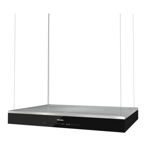
Klugmann DORMAGEN User manual


DEAR CUSTOMERS
Congratulations to you to make the right choice. Our devices are
designed and manufactured to meet your expectations and certainly will be
part of the modern-equipped household. We believe that a modern, functional
and practical appliance, made from top quality materials, will meet all your
requirements.
Prior to installation and use of the purchased hood, please read the contents
of this manual, as well as safety rules presented therein. We wish you a lot of
satisfaction from the choice of the hood of our company.
NOTE:
•
During installation, observe the existing regulations for air evacuation.
•
When the chimney hood is used at the same time as appliances
combusting gas or other fuels, the room should be well ventilated. Air
from the hood should not be discharged into the flue duct used to
exhaust the devices combusting gas or other fuels.
•
Before connecting the hood to the power supply, make sure the voltage
and frequency of the supply current corresponds to that given on the
nameplate. The hood must be connected to an easily accessible outlet.
It is unacceptable to remove the plug and permanently connect the
hood to power supply.
•
if cleaning and maintenance is not carried out in accordance with the
instructions, there is a risk of fire.
•
If you use a gas stove, do not leave an open flame.
•
The equipment is not intended for use by persons (including children)
with reduced physical, sensory or mental capabilities.
•
The equipment is not designed for children to play.
•
If the non-detachable supply cord is damaged, it should be replaced by
a special cord or assembly available from the manufacturer or our
customer service.
•
The manufacturer is not liable for failure to comply with regulations for
the installation and maintenance and improper handling of the hood.
Accessible parts may become hot during cooking on the stove.

1. GENERAL INFORMATION
DORMAGEN hood is designed to remove kitchen fumes in an external
venting mode (ducts routed outside) or in a re-circulation mode (internal
circuit). It is designed for mounting above a gas or electric hob. It has an
independent lighting and exhaust turbine, which can be set to one of five
rotation speeds.
NOTE:
Please keep your proof of purchase along with the warranty card stamped for
possible complaints. Without these documents, the warranty is void.
The manufacturer disclaims liability for any damage or injury resulting
from the installation and used not in accordance with instructions contained
herein.
2. SPECIFICATIONS
FEATURES DORMAGEN
Rated voltage 230V-50Hz
Maximum power usage 257 W
Motor power 250 W
Lighting power 4 x 2 W
Max. capacity. 800 m
3
/h
Appliance class second
Operation continuous, supervised

3. DIMENSIONS
DORMAGEN
A - 90
Fig.1

4. INSTALLATION
4.1 SETTING HOOD OPERATION MODE
DORMAGEN hood can operate in two modes:
1.
External venting (Fig.3a) - evacuation of air outside the building by
connecting the hood with the air duct via a rigid plastic tube Ø150mm or
Ø120mm with a reducing union.
2.
Re-circulation (Fig.3b) - internal circulation of air, using carbon filters
(Fig.2).
Fig.2
When the internal circuit is used it is necessary to install the carbon
filters (Fig.2). The air purified through the filters returns into circulation via an
outlet opening.
Carbon filters should be replaced at least once every 3 months (depending on
the intensity of the cooking).
a) EXTERNAL VENTING b) RE-CIRCULATION
Fig.3

NOTE:
The air from the hood should not be discharged into the chimney
channel used to exhaust the appliances combusting gas or other fuels.
4.2 ELECTRICAL CONNECTION
Before connecting the hood to the power supply, make sure the voltage
and frequency of the supply current corresponds to that given on the
nameplate. The hood must be connected to an easily accessible outlet. It is
unacceptable to remove the plug and permanently connect the hood to power
supply. The hood must be connected to the power supply after this assembly.
5. ASSEMBLY
The distance "A" between the lowest part of the chimney hood and a
supporting surface of cooking utensils should be min. 65 cm for a gas stove
(Fig.4).
During assembly, observe the existing regulations for air evacuation.
When the chimney hood is used at the same time as appliances combusting
gas or other fuels, the room should be well ventilated.
In order to achieve optimal air evacuation use a rigid plastic duct with a cross-
section Ø150 mm or Ø120mm downstream the reducing union.
Fig. 4

5.1 COMPONENTS FOR ASSEMBLY
1- upper mask (internal)
2- lower mask (external)
3- hood body
4- glass
5- aluminium grease filter
6- ceiling plate
7 – four angles
8 – four dowels 6x60 mm
9 – screws 3,9x6,5 mm
10 – four screws M4x20 with washers
8 9 10
Fig.5
5.2 ASSEMBLY OF ANGLES
Screw the four angles (Figure 7) to the hood body. Each of the angles
should be fastened with at least four screws. The height to which the angles
should be pulled out can be calculated from the relationship, which is shown
in Figure (Fig.7)
6
7

Fig.6
DORMAGEN
Fig.7

A≤C-B -D
where:
A – height to which the angles should be pulled out,
B – distance from the hob to the lower surface of the hood,
C – distance from the ceiling to the hob,
D – distance from the lower surface of the hood to the top surface of the
hood.
5.3 GLASS ASSEMBLY
Put the glass on the hood body and then
tighten it with the screw (3) M4x20 with
a conical washer (2) and the rubber
washer (1). (Fig.8).
Fig.8
5.4 HOOD TO CEILING ASSEMBLY
Peel off the protective film from the masks. Place the masks on the hood
body with screwed angles and glass in such a way that the inner mask vents
are at the top. Before installation, make sure that the ceiling may transfer the
weight of the hood. Do not mount the hood directly to the plasterboard panels
of suspended ceilings. Clearly indicate the mounting location on the ceiling in
accordance with Figure 9. Spacing of the holes on the ceiling board is
204mm. The holes for fixing dowels should be drilled in the ceiling with φ 8
mm drill. Fix the ceiling board to the ceiling by means of dowels (Note: Be
sure to use steel washers that are provided).

Hood
dimensions A
60 198
90 348
120 498
Fig.9
Screw the hood to the ceiling plate (this requires great caution, because
the hood has a large mass). Each of the four angles should be fastened with
two screws in such a way that the angles are within the ceiling plate (Fig.10).
If the hood is to operate in a mode of external venting, you must install the
plastic pipe, connecting the hood turbine outlet with a ventilation channel.
Then, the hood must be connected to the mains. The last step is to screw the
inner mask to the ceiling plate (Fig.10).
Fig.10
Table of contents
Languages:
Other Klugmann Ventilation Hood manuals