Klein Tools ET160 User manual

INSTRUCTION MANUAL
FRANÇAIS pg. 13
ESPAÑOL pg. 7
Refrigerant Gas
Leak Detector
• DETECTS CFC’S,
HFC’S, HCFC’S,
AND BLENDS
• AUTO-ZEROS
AT START-UP
• 18 INCH
GOOSENECK
PROBE FOR
EASY ACCESS
ENGLISH
2m
ET160
Refrigerant Gas
Leak Detector
DETECTS CFC’S,
HFC’S, HCFC’S,
5001748

2
GENERAL SPECIFICATIONS
Klein Tools’ ET160 is an easy-to-use tester that provides audible and
visual alarms in the presence of CFC’s, HFC’s, HCFC’s and blends. Detect
as low as 100 ppm of common refrigerant gases.
• Audible Alert: 85 db ticking, modulation proportional to gas
concentration
• Visual Alert: 5× blue LED,
illumination proportional to gas concentration
• Range*: 100 to 3,000 ppm
LOW sensitivity* (white light): 200 to 3,000 ppm
HIGH sensitivity* (yellow light): 100 to 1,000 ppm
• Initial calibration: 50 seconds to zero calibration
• Response time (after calibration): 3 seconds
• Sensor: Heated diode
• Sensor Life expectancy: 5 years
• Probe: 18" (457 mm) gooseneck
• Batteries: 4× AAA alkaline
• Operating Altitude: 6562 ft. (2000 m)
• Relative Humidity: <80% non-condensing
• Operating Temp: 32°to 122°F (0°to 50°C)
• Storage Temp: -4°to 122°F (-20°to 50°C)
• Dimensions: 8.11" × 2.72" × 1.75" (206 × 69 × 45 mm)
• Weight: 15 oz. (425 g) including batteries
• Tripod Mount: 1/4-20 UNC
• Drop Protection: 6.6 ft. (2m)
• Standards: EN14624:2020
*Based on R-134A. Other gases or mixtures will have different values.
Specifications subject to change.
WARNINGS
To ensure safe operation and service of the tester, follow these
instructions. Failure to observe these warnings can result in severe
injury or death. Know the characteristics of the gas you are working
with and use proper precautions to avoid hazardous conditions.
• Read, understand, and follow all instructions to ensure safe operation.
• Always turn on the gas detector in an area known to be free of gases.
• Initial calibration should be performed in an area known to be free of
refrigerant gases. Calibration in an area containing refrigerant gas will
result in incorrect calibration and lower than actual readings. This could
result in refrigerant gases not being detected.
• The refrigerant gas leak detector is NOT intended as a personal protection
device (PPE).
• The refrigerant gas leak detector is NOT insulated. Avoid contact with areas
where energized conductive elements may be present. Shut off power to
the area before starting measurements.
• Do NOT probe moving machinery that could catch any part of the meter
and cause harm to the operator and the meter.
• Always wear approved eye protection.
ENGLISH

3
FEATURE DETAILS
NOTE: There are no user-serviceable parts inside tester.
1. Gooseneck 9.Auto Power-Off (APO) Button
2. Gooseneck Clip 10.LOW Sensitivity Mode Button
3. Sensor Head 11.HIGH Sensitivity Mode Button
4. Indicator Lights 12.HOLD Button
5. LOW Sensitivity Light 13.Power Button
6. HIGH Sensitivity Light 14.1/4-20 UNC Tripod Mount
7. Auto-Zero Button 15.Battery Door
8. Mute Button 16.Battery Cartridge (inside battery compartment)
Front of
Tester Back of
Tester
1
5
8
7
10
13
11
12
6
9
4
16
2
14
15
3

4
FUNCTION BUTTONS
AUTO-ZERO BUTTON
7
Press to set zero point calibration in a known clean environment.
MUTE BUTTON
8
Press to mute the audible alarm. Visual indicators will continue to
function as normal
.
AUTO POWER-OFF (APO) BUTTON
9
Press to enable or disable the Auto Power-Off feature. When enabled,
the button will illuminate blue, and the tester will automatically power
off after 10 minutes of inactivity.
LOW BUTTON
10
Press to enter Low Sensitivity mode (200 to 3,000 ppm). White light will
blink.
HIGH BUTTON
11
Press to enter High Sensitivity mode (100 to 1,000 ppm). Yellow light
will blink.
HOLD BUTTON
12
Press to lock the current measurement on the display. Press again to
return to taking active measurements.
POWER BUTTON
13
Press and hold for 3 seconds to turn tester on or off.
ENGLISH
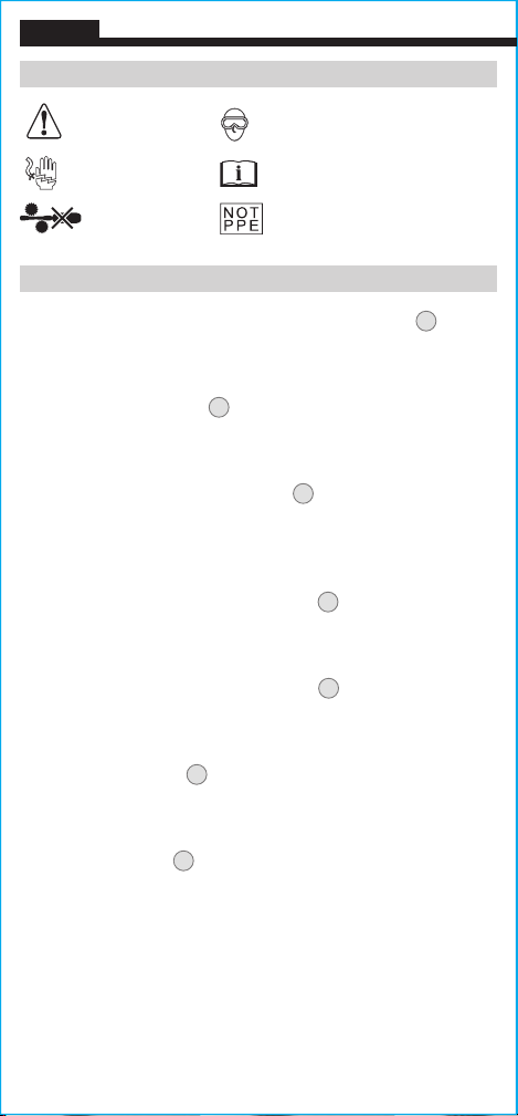
SYMBOLS ON METER
Warning
Risk of
Electric Shock
Wear approved eye protection
Read instructions
Not intended for use as Personal
Protective Equipment (PPE)
Do NOT probe
moving machinery

5
OPERATING INSTRUCTIONS
1. In an area where gas is known to be not present, press the
power button
13
for 3 seconds. The tester will beep and start a
50-second zero-calibration process while the first indicator light
(blue)
4
blinks. Once complete, all indicator lights
4 5 6
will blink for one second, then the HIGH indicator light
6
will
illuminate and continue to flash, indicating it is ready to take a
measurement.
2. Start measuring in the High sensitivity mode (100 to 1,000 ppm).
To view higher values (200 to 3,000 ppm), press the LOW button
10
to enter Low sensitivity mode.
3. Point the sensor
3
towards the area to test. If all blue indicator
lights are illuminated in High sensitivity mode, switch to Low
sensitivity mode by pressing the LOW button
10
.
NOTE: Changing from High to Low sensitivity mode may cause
some of the indicator lights to turn off.
4. As you get closer to the source of a leak, the concentration levels
detected will increase, as indicated by increasing audible/visual
alarms. Move the sensor head in the direction of increasing
audible/visual alerts to the source of the leak.
WARNING: High concentrations of refrigerant gases can cause
asphyxia and other hazards that could cause serious personal
injury or death. Know the characteristics of the gas you are
working with and use proper precautions to avoid hazardous
conditions.

6
ENGLISH
CLEANING
Be sure tester is turned off and wipe with a clean, dry lint-free
cloth.
Do not use abrasive cleaners or solvents.
STORAGE
Remove the batteries when the tester is not in use for a prolonged
period of time. Do not expose to high temperatures or humidity.
After a period of storage in extreme conditions exceeding the limits
mentioned in the General Specifications section, allow the tester to
return to normal operating conditions before using.
WARRANTY
www.kleintools.com/warranty
DISPOSAL /RECYCLE
Do not place equipment and its accessories in the trash.
Items must be properly disposed of in accordance with
local regulations. Please see www.epa.gov or
www.erecycle.org for additional information.
CUSTOMER SERVICE
KLEIN TOOLS, INC.
450 Bond Street Lincolnshire, IL 60069 1-800-553-4676
[email protected] www.kleintools.com
MAINTENANCE
BATTERY REPLACEMENT
When the LOW alert
5
and HIGH alert
6
lights
are illuminated at the
same time, the batteries must be replaced.
1. Loosen screw and remove
battery door
15
.
2. Remove battery cartridge
16
from battery compartment.
Note orientation.
3. Remove and recycle
4 spent AAA batteries.
4. Install 4 new AAA batteries into
cartridge, noting proper polarity.
5. Place battery cartridge back into the
battery compartment, aligning the
leads (fits only one way).
6. Replace battery door and tighten screw securely.
SENSOR SERVICING
When ALL lights on the tester
4
,
5
,
6
,
7
,
9
are illuminated, the
sensor
3
has failed and the unit must be serviced. Contact Klein Tools
at 1-800-553-4676 or [email protected] for further
details.
There are no user-serviceable parts inside tester.
15
16

MANUAL DE INSTRUCCIONES
Detector de fugas
de gas refrigerante
• DETECTA CFC, HFC,
HCFC Y MEZCLAS
• CALIBRACIÓN
AUTOMÁTICA
DELCERO
AL ENCENDER
• SONDA CUELLO
DE CISNE
DE 18" PARA
FÁCIL ACCESO
ESPAÑOL
2m
ET160
Detector de fugas
de gas refrigerante
DETECTA CFC, HFC,
HCFC Y MEZCLAS
SONDA CUELLO
5001748

8
ESPECIFICACIONES GENERALES
El ET160 de Klein Tools es un probador fácil de utilizar que emite alarmas
audibles y visuales ante la presencia de clorofluorocarbonos (CFC),
hidrofluorocarbonos (HFC), hidroclorofluorocarburos (HCFC) y mezclas. Detecta
gases refrigerantes comunes en concentraciones tan bajas como 100ppm.
• Alarma audible: tictac de 85dB, con modulación proporcional a la
concentración de gas
• Alarma visual: 5LED azules,
con iluminación proporcional a la
concentración de gas
• Rango*: 100 a 3000ppm
Sensibilidad LOW (baja)* (luz blanca): 200 a 3000ppm
Sensibilidad HIGH (alta)* (luz amarilla): 100 a 1000ppm
• Calibración inicial: 50segundos para calibración del cero
• Tiempo de respuesta (después de la calibración): 3segundos
• Sensor: diodo calentado
• Vida útil esperada del sensor: 5años
• Sonda: cuello de cisne de 18" (457mm)
• Baterías: 4baterías alcalinasAAA
• Altitud de funcionamiento: 6562' (2000m)
• Humedad relativa: <80%, sin condensación
• Temperatura de funcionamiento: 32 a 122°F (0 a 50°C)
• Temperatura de almacenamiento: -4 a 122°F (-20 a 50°C)
• Dimensiones: 8,11"×2,72"×1,75"(206×69×45mm)
• Peso: 15oz (425g) incluidas las baterías
• Montaje en trípode: 1/4-20UNC
• Protección ante caídas: 6,6' (2m)
• Normas: EN14624:2020
*Con base en R-134A. Otros gases o mezclas de gases tendrán valores diferentes.
Especificaciones sujetas a cambios.
ADVERTENCIAS
Para garantizar el funcionamiento y servicio seguros del probador,
siga estas instrucciones. El incumplimiento de estas advertencias
puede provocar lesiones graves o la muerte. Infórmese sobre las
características del gas con el que trabaja y emplee las medidas de
precaución pertinentes para evitar situaciones de riesgo.
• Lea, comprenda y respete todas las instrucciones para garantizar un
funcionamiento seguro.
• Siempre encienda el detector de gas en un área donde se sabe que no hay
presencia de gases.
• La calibración inicial debe realizarse en un área donde se sabe que no hay
presencia de gases refrigerantes. De lo contrario, la calibración no será
correcta y las mediciones serán inferiores a las reales. Esto podría dar lugar a
que los gases refrigerantes no se detecten.
• El detector de fugas de gas refrigerante NO está diseñado para que se lo use
como equipo de protección personal (PPE).
• El detector de fugas de gas refrigerante NO cuenta con aislamiento. Evite el
contacto con áreas donde pueda haber elementos conductores energizados.
Antes de comenzar a medir, apague el suministro de energía hacia estas áreas.
• NO utilice la sonda en máquinas en movimiento que puedan atrapar alguna
pieza del medidor y provocar lesiones al operador y daños al dispositivo.
• Siempre debe usar protección para los ojos aprobada.
ESPAÑOL

9
DETALLES DE LAS CARACTERÍSTICAS
NOTA: el probador no contiene en su interior piezas que el usuario
pueda reparar.
1.
2.
3.
4.
5.
6.
7.
8.
Cuello de cisne
Sujetador del cuello de cisne
Cabeza del sensor
Luces indicadoras
Luz de sensibilidad LOW (BAJA)
Luz de sensibilidad HIGH (ALTA)
Botón AUTO ZERO (Calibración
automática del cero)
Botón de silenciamiento
9.
10.
11.
12.
13.
14.
15.
16.
Botón de apagado automático (APO)
Botón LOW Sensitivity
(Modo de sensibilidad baja)
Botón HIGH Sensitivity
(Modo de sensibilidad alta)
Botón “HOLD” (RETENER)
Botón de encendido
Montaje en trípode para 1/4-20UNC
Tapa del compartimiento de baterías
Cartucho de baterías
(dentro del compartimiento de baterías)
Parte frontal
del probador Parte posterior
del probador
1
5
8
7
10
13
11
12
6
9
4
16
2
14
15
3
10
BOTONES DE FUNCIONES
BOTÓN AUTO-ZERO (CALIBRACIÓN AUTOMÁTICA DEL CERO)
7
Presione este botón para establecer el punto cero de calibración en un
ambiente puro conocido.
BOTÓN DE SILENCIAMIENTO
8
Presione este botón para silenciar la alarma audible. Los indicadores visuales
seguirán funcionando normalmente
.
BOTÓN DE APAGADO AUTOMÁTICO (APO)
9
Presione este botón para activar o desactivar la función de apagado
automático. Al activarla, el botón se iluminará en azul y el probador
seapagará automáticamente después de 10minutos de inactividad.
BOTÓN LOW (MODO DE SENSIBILIDAD BAJA)
10
Presione este botón para ingresar al modo de sensibilidad baja
(200a3000ppm). Parpadeará la luz blanca.
BOTÓN HIGH (MODO DE SENSIBILIDAD ALTA)
11
Presione este botón para ingresar al modo de sensibilidad alta
(100a1000ppm). Parpadeará la luz amarilla.
BOTÓN HOLD (RETENER)
12
Presione este botón para retener la medición en curso en la pantalla.
Presione nuevamente para volver a tomar las mediciones activas.
BOTÓN DE ENCENDIDO
13
Manténgalo presionado durante 3segundos para encender o apagar el
probador.
ESPAÑOL
SÍMBOLOS EN EL PROBADOR
Advertencia
Riesgo de
choque eléctrico
Use protección para los ojos aprobada
Lea las instrucciones
No diseñado para usarlo como
equipo de protección personal (PPE)
NO utilizar la sonda
en máquinas en
movimiento
Other manuals for ET160
1
Table of contents
Languages:
Popular Gas Detector manuals by other brands

Macurco
Macurco GD-6 Operation manual

Evikon
Evikon E2632 user manual

Critical Environment Technologies
Critical Environment Technologies CGAS-A Series Installation & operation manual

MSA
MSA altair 5 operating manual

DOD Technologies
DOD Technologies ChemLogic CL96 operating manual

DEGA
DEGA NS III LCD Series instruction manual


