Kaysun KCCHT-02 User manual

OWNER’S MANUAL
Central Heat Pump Heater
Wire Controller
IMPORTANT NOTE:
Thank you for purchasing our product.
Before using your unit, please read this manual carefully and keep it for future
reference.
KCCHT-02

• This manual gives detailed description of the precautions that should be brought to your
attention during operation.
• In order to ensure correct service of the wired controller please read this manual carefully
before using the unit.
• For convenience of future reference, keep this manual after reading it.

ÍNDEX
1. Safety precautions...........................................................................1
2. Overview of wire controller ..............................................................3
3. Whole instruction of wire controller..................................................4
4. Operation instruction .......................................................................6
5. Error alarm handling.......................................................................14
ATTACHED PICTURE (I)...................................................................15

1
1. Safety precautions
The following contents are stated on the product and the operationmanual, includ-
ing usage, precautions against personal harm and property loss, and the methods
of using the product correctly and safely. After fully understanding the following
contents (identiers and icons), read the text body and observe the following rules.
■ Identier description
Identier Meaning
Warning Means improper handling may lead to severe injury.
Caution Means improper handling may lead to personal injury or property loss.
[Note]:
1. “Harm” means injury, burn and electric shock which need long-term treatment but need no
hospitalization.
2. “Property loss” means loss of properties and materials.
■ Icon description
lcon Meaning
It indicates forbidding. The forbidden subject-matter is indicated in the icon or by
images or characters aside.
It indicates compulsory implementation. The compulsory subject-matter is indica-
ted in the icon or by images or characters aside.
Warning
Warning
Delegate
installation
Please entrust the distributor or professionals to install the unit. The insta-
llers must have the relevant know- how.Improper installation performed by
the user without permission may cause re, electric,
shock, personal injury or water leakage.
Usage Warning
Forbid Do not spray ammable aerosol to the wire controller directly. Otherwise,
re may occur.
Forbid Do not operate with wet hands or let water enter the wire controller.
Otherwise, electric shock may occur.

2
WARNING
• Please entrust the distributor or professionals to install the unit.
• Imporper installation may lead to electric shock or re.
CAUTION
• For protecting the device, do not repeatedly or quickly shift modes. Each wire controller operation to off
the unit, it must be waited for 3 minutes or waited for all the units stopped then can re-operate the wire
controller to start the outdoor unit.
• The wire controller is supplied 10V AC current by the adapter.
• Do not install the unit in a place vulnerable to leakage of ammable gases. Once ammable gases are
leaked and left around the wire controller, re may occur.

3
2. Overview of wired controller
2.1 Basic conditions of operating the wired controller.
1) Applicable range of supply voltage:Input voltage is 10V AC.
2) Operating environment temperature of wired controller: -10°C~+43°C.
3) Operating RH of wired controller: RH 40%~RH90%.
2.2 Main functions of this wire controller as follows:
1) Touch key operation;
2) LCD displays operation parameters;
3) Multiple timer;
4) Buzzer prompt tone and alarm functions;
5) Real-time clock function.

4
3. Whole instruction of wire controller
1. Operation icon
2. Mode area
3. Setting temperature
4. Timing On/Off
5. Function Icon
6. On-line Unit Qty. Indication
7. Reserved
8. Clock
9. Water temp.
10. ON/OFF Key
11. Right, Left Right Key
12. OK key
13. Setting key
14. Add, Reduce key
15. Cancel key
16. Reserved. key

5
1. Operation icon : Indicate the ON and OFF status; when it is ON, it will display; when it is OFF, it
will disappear;
2. Mode area: Indicate the main unit operating mode; details refer to Page 15;
3. Setting temperature: 2 status can be displayed:
4. Timing ON/OFF indication : Indicate the timing information; details refer to Page 10;
5. Function icon
1) Computer: Display when connects to computer;
2) Maintenance: When the icon is lighted on it means should arrange professionals to do
the cleaning maintenance; long press “AUXILIARY” for 3 seconds then this icon will be off, until the next
maintenance;
3) E-heating: Display when the electric auxiliary heating water function is operated;
4) Check: Display when check function is operated;
5) Anti-freezing: Display when the main unit ambient temperature is below 2ć, to remind the
main unit should be do the anti-freezing measurement;
6) Lock: When the icon is lighted on, it means the button has been locked (no keys operation
for 2 minutes ), long press “OK” key for 3 seconds to unlock;
7) Error: When the main unit has error or protection, this icon will be displayed. The unit need
to be maintained by professionals.
6. On-line unit qty. indication: Under normal status display the quantity of the units connected to the wire
controller; under check status display the device serial number;
7. Reserved;
8. Clock: Under normal status display clock; during timing setting it displays the setting timing time, details
refer to Page 10;
9. Water temperature: Under normal status display water temperature; during water temperature setting it
displays the setting numerical value; under the check status display check parameter;
10. ON/OFF key: On and Off functions;
11. Right, Left key: Under main page to press this key can query the setting water temperature, setting
timing etc; during timing setting press the right key then shift to the next step setting; during spot check
they are used to turn over the unit parameter information;
12. OK key: After setting the parameter then press this key to conrm. After keys locking then long press this
key for 3 seconds to unlock;
13. Setting key: Setting the water temperature, timing, mode etc, long press this key for 3 seconds enter to
the check;
14. Add, Reduce key: Setting water temperature, timing, water level etc; during spot check they are used to
read over #0#15 units;
15. Cancel key: During setting parameters press this key to cancel setting. After timing setting and then long
press this key 3 seconds to cancel timing;
16. Reserved key.
6
4. Operation instruction
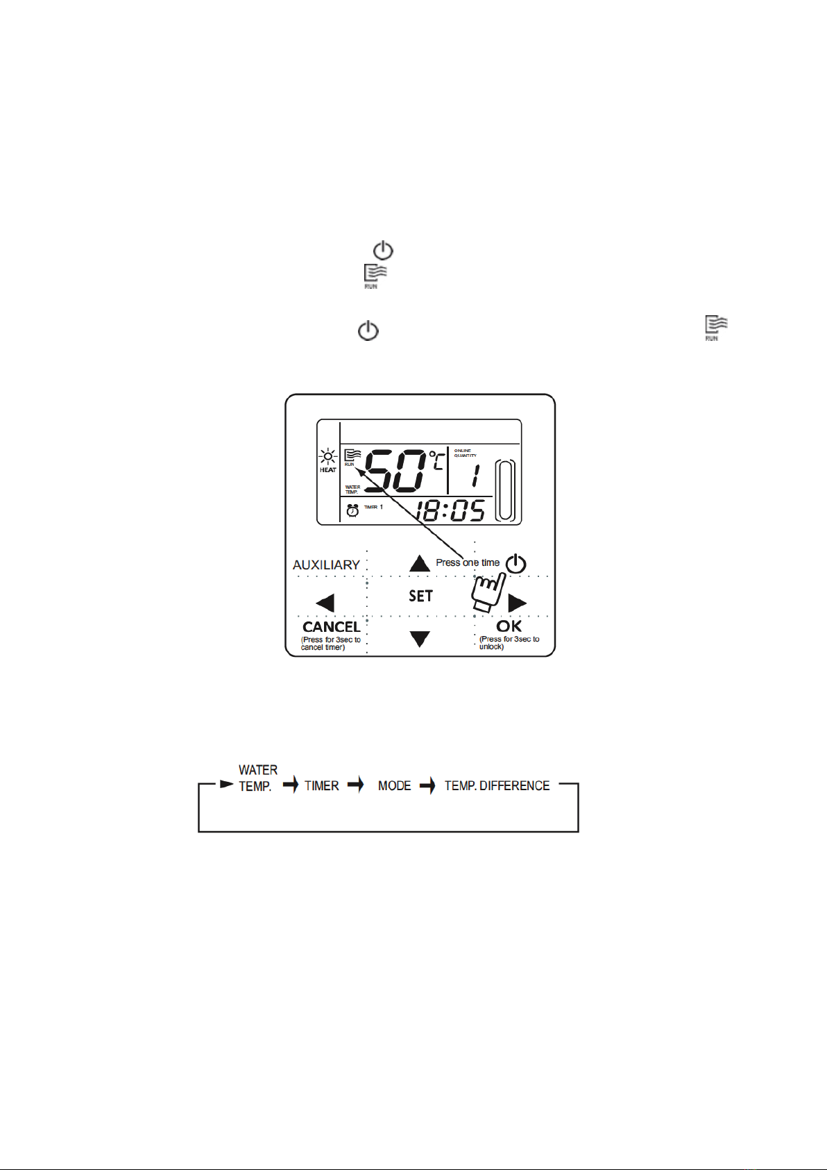
4.1. On and Off the main unit
1. Press the On/Off key to control On and Off status of the main unit.
2. Under Off status, press the On/Off key “ ” to operate the main unit, at that time the LCD of wire
controller will display the operation icon “ ”. The main unit will be operated as the current setting of the
wire controller.
3. Under On status, press the On/Off key “ ” to off the main unit, at that time the operation icon “ ” on
the LCD of wire controller will disappear.
4.2. Setting operating modes and parameters
Press “Setting” key to enter the operation mode and parameters setting. The setting contents will change as
the following order each time the key is pressed:
1) Setting water temperature: under main page directly press the “▲” or “▼” to adjust the water temperature,
or press “Setting” key to enter and then press “▲” or “▼” to adjust. At that time the LCD will display “Setting
temperature” and “Water temperature parameter”, as the following display. Query water temperature setting:
press the “t” or “ u” key under the main page to query the set water temperature numerical value.
Fig.4-1

7
2) Timing setting: can set 3 timing periods on the wire controller: Timer 1, Timer 2, Timer 3, and then control
the main unit to ON and OFF in different periods. Setting method: press “Setting” key under main page twice
to enter timing setting. At that time the LCD will display as the following:
This time the hour of the clock will ash, it means the current setting is the hour of Timer 1 “On”, press the “▲”
or “▼” to adjust, press “ ” key when nished, and then the minute of the clock will ash, it means the current
setting is the minute of Timer 1 “On”, press the “▲” or “▼” to adjust, press “ ” key when nished, the LCD will
display as the following:
Fig.4-2
Fig.4-3
Fig.4-4
Fig.4-5
Table of contents
Other Kaysun Remote Control manuals

Kaysun
Kaysun KID-02 S User manual

Kaysun
Kaysun KID-05.1 S KID-05 S User manual

Kaysun
Kaysun KID-02 S User manual

Kaysun
Kaysun KCT-03 SRPS Installation instructions

Kaysun
Kaysun KI-04 S Quick start guide

Kaysun
Kaysun KCCHT-03 Operating and maintenance instructions

Kaysun
Kaysun KID-03 User manual

Kaysun
Kaysun KI-03 S Installation instructions

Kaysun
Kaysun KID-05.1 S KID-05 S User manual

Kaysun
Kaysun KC-03 SPS Installation instructions


